Methods of improving surface roughness of an environmental barrier coating and components comprising environmental barrier coatings having improved surface roughness

a technology of environmental barrier coating and surface roughness, which is applied in the direction of mechanical equipment, machines/engines, transportation and packaging, etc., can solve the problems of unsatisfactory problems and ebc having a surface roughness greater than 200, and achieve the effect of improving the surface roughness of an environmental barrier coating

Inactive Publication Date: 2011-02-03
GENERAL ELECTRIC CO
View PDF13 Cites 30 Cited by
  • Summary
  • Abstract
  • Description
  • Claims
  • Application Information

AI Technical Summary

Benefits of technology

[0005]Embodiments herein generally relate to methods for improving surface roughness of an environmental barrier coating comprising: providing a component having a plasma sprayed environmental barrier coating; applying a slurry to the environmental barrier coating of the component, the slurry comprising a transition layer slurry or an outer layer slurry; drying the environmental barrier coating having the applied slurry; and sintering the component to produce a component having an improved surface roughness wherein the slurry comprises: a solvent; a primary transition material, or a primary outer material; and a slurry sintering aid selected from the group consisting of iron oxide, gallium oxide, aluminum oxide, nickel oxide, titanium oxide, boron oxide, alkaline earth oxides, carbonyl iron, iron metal, aluminum metal, boron, nickel metal, iron hydroxide, gallium hydroxide, aluminum hydroxide, nickel hydroxide, titanium hydroxide, alkaline earth hydroxides, iron carbonate, gallium carbonate, aluminum carbonate, nickel carbonate, boron carbonate, alkaline earth carbonates, iron oxa

Problems solved by technology

Unfortunately, there can be some undesirable issues associated with standard, industrial coating processes such as plasma spray and vapor deposition (i.e. chemical vapor deposition, CVD, and electron beam physical vapor deposition, EBPVD) currently used

Method used


Image

  • Methods of improving surface roughness of an environmental barrier coating and components comprising environmental barrier coatings having improved surface roughness
  • Methods of improving surface roughness of an environmental barrier coating and components comprising environmental barrier coatings having improved surface roughness
  • Methods of improving surface roughness of an environmental barrier coating and components comprising environmental barrier coatings having improved surface roughness

Examples


example 1

[0079]A silicon bond coat was applied to a SiC—SiC CMC using a conventional air plasma spray process. Next, a primary transition material slurry was made by first mixing ytterbium disilicate (primary transition material), iron oxide nanoparticles (sintering aid), ethanol (solvent), and polyethylenimine (dispersant) in a plastic container, along with enough 0.25 inch (6.35 mm) diameter, spherical zirconia media to line the bottom of container. This mixture was placed on a roller mill for 15 hours. After taking the container off of the roller mill, the zirconia media was removed and the slurry was filtered through a 325 mesh screen to remove any large particle agglomerates.

[0080]The resulting primary transition material slurry (Slurry A) consisted of 56.11% ytterbium disilicate, 0.54% iron oxide, 0.57% polyethylenimine, and the balance ethanol (all percents by weight). The silicon-coated ceramic component was dipped into Slurry A, dried in ambient conditions, re-dipped into Slurry A, ...

example 2

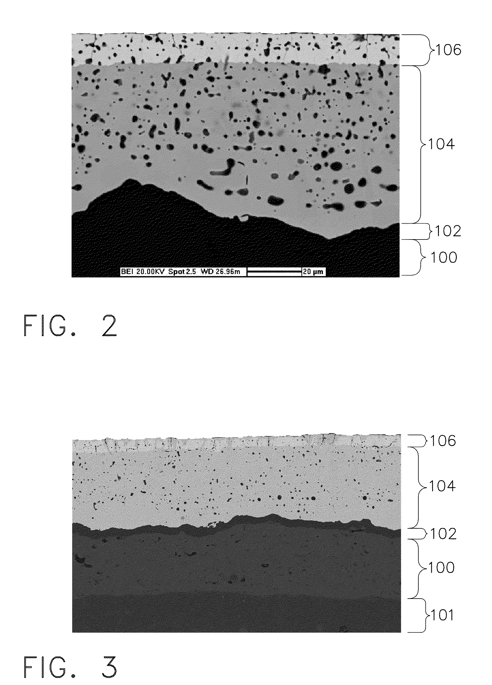
[0084]A CMC (101) coated with the EBC of Example 1 was exposed to 2400° F. (1316° C.) steam for 1000 hours. FIG. 3 shows a SEM micrograph of this coating after high temperature steam exposure with silicon bond coat (100), a silica layer (102) that has grown to approximately 7.0 micrometer thickness, an iron-doped ytterbium disilicate transition layer (104), and a dense ytterbium monosilicate outer layer (106) with cracks. Some ytterbium disilicate has formed around the cracks in the monosilicate layer as an artifact of high gaseous silicon content in the static atmosphere of the steam test.

example 3

[0085]To demonstrate proof of principle, a primary transition layer was deposited on a silicon metal wafer using a slurry deposition process. A primary transition material slurry was made by first mixing ytterbium disilicate powder (primary transition material), gallium oxide powder (sintering aid), ethanol (solvent), and polyethylenimine (dispersant) in a plastic container, along with enough 0.25 inch (6.35 mm) diameter, spherical zirconia media to line the bottom of container. This mixture was placed on a roller mill for 15 hours. After taking the container off of the roller mill, the zirconia media was removed and the slurry was filtered through a 325 mesh screen to remove any large particle agglomerates.

[0086]The resulting primary transition material slurry (Slurry C) consisted of 56.35% ytterbium disilicate, 0.64% gallium oxide, 0.57% polyethylenimine, and the balance ethanol (all percents by weight). The silicon-coated ceramic component was dipped into Slurry C, dried in ambie...


PUM

PropertyMeasurementUnit
Temperatureaaaaaaaaaa

Abstract

Methods for improving surface roughness of an environmental barrier coating including providing a component having a plasma sprayed environmental barrier coating; applying a slurry to the environmental barrier coating of the component, the slurry being a transition layer slurry or an outer layer slurry; drying the environmental barrier coating having the applied slurry; and sintering the component to produce a component having an improved surface roughness where the slurry includes a solvent; a primary transition material, or a primary outer material; and a slurry sintering aid selected from iron oxide, gallium oxide, aluminum oxide, nickel oxide, titanium oxide, boron oxide, alkaline earth oxides, carbonyl iron, iron metal, aluminum metal, boron, nickel metal, iron hydroxide, gallium hydroxide, aluminum hydroxide, nickel hydroxide, titanium hydroxide, alkaline earth hydroxides, iron carbonate, gallium carbonate, aluminum carbonate, nickel carbonate, boron carbonate, alkaline earth carbonates, iron oxalate, gallium oxalate, aluminum oxalate, nickel oxalate, titanium oxalate, solvent soluble iron salts, solvent soluble gallium salts, solvent soluble aluminum salts, solvent soluble nickel salts, solvent titanium salts, solvent soluble boron salts, and solvent soluble alkaline earth salts.

Description

CROSS REFERENCE TO RELATED APPLICATIONS[0001]This Application claims priority to U.S. Provisional Application Ser. No. 61 / 230,303, filed Jul. 31, 2009, which is herein incorporated by reference in its entirety.TECHNICAL FIELD[0002]Embodiments described herein generally relate to methods of improving surface roughness of an environmental barrier coating and components comprising environmental barrier coatings having improved surface roughness. More particularly, embodiments described herein generally relate to improving surface roughness of environmental barrier coatings using solvent-based slurries comprising at least one sintering aid.BACKGROUND OF THE INVENTION[0003]Environmental barrier coatings (EBCs) are often utilized to protect engine components for harsh conditions present in high temperature engine environments. EBCs can provide a dense, hermetic seal against the corrosive gases in the hot combustion environment and can help prevent dimensional changes in the component due ...

Claims


Application Information

Patent Timeline
IPC IPC(8): B32B33/00B05D3/10
CPCC04B41/009C04B41/52C04B41/89F05B2230/22F05B2230/312Y10T428/239F05B2230/90C04B41/4527C04B41/5096C04B41/4539C04B41/4549C04B41/5024C04B41/5027C04B35/565C04B35/584C04B35/806
Inventor KIRBY, GLEN HAROLDBOUTWELL, BRETT ALLEN
Owner GENERAL ELECTRIC CO
Why Eureka
Try Eureka