Coating composition

Inactive Publication Date: 2003-03-04
JSR CORPORATIOON
View PDF10 Cites 65 Cited by
  • Summary
  • Abstract
  • Description
  • Claims
  • Application Information

AI Technical Summary

Problems solved by technology

However, further improvements have been anticipated in the formation of the silicon film by these CVD's in view of the following points regarding processing; that is, (a) since it is a gas phase reaction, the generation of silicon particles in a gas phase causes the contamination of an apparatus or the inclusion of foreign matters, thereby causing low production yield, (b) since the material is in gaseous form, it is difficult to form a film having a uniform thickness on a substrate whose surface is not smooth, (c) productivity is low because the formation of the film is slow, and (d) complicated and expensive radio-frequency generator and vacuum apparatus are required in the case of plasma CVD.
Further, since gaseous silicon hydride which is highly toxic and highly reactive is used as the material, it is not only difficult to handle but also requires a sealed vacuum apparatus since it is in gaseous form.
In general, these apparatus are not only bulky and expensive but also consume a large amount of energy in a vacuum or plasma system, causing an increase in product cost.
This process, however, has some points to be improved in that a complicated apparatus is required because the gasification and subsequent cooling of silicon hydride as the material are conducted in succession and that it is difficult to control the thickness of the film.
This process has such problems that the system is difficult to handle because it is unstable and that it is difficult to obtain a uniform film thickness when the silicon hydride is applied to a substrate having a large area because it is in liquid form.
This polymer, however, cannot be used for forming a film by coating since it is insoluble in a solvent.
However, this process has such defects that it has too many steps for forming a device across a large area and that it raises production costs because of the use of expensive apparatus and a variety of materials and the consumption of a large amount of energy.
Since the doping is carried out in a vacuum process control thereof is complicated, and it is particularly difficult to form a uniformly doped silicon film on a large substrate.
When n is smaller than 4, a multiple aggregate of silicon atoms becomes thermodynamically unstable, whereby the polycyclic silicon compound becomes difficult to handle.
When the boiling point of the solvent is

Method used


Image

  • Coating composition
  • Coating composition
  • Coating composition

Examples


Example

Synthesis Example 1

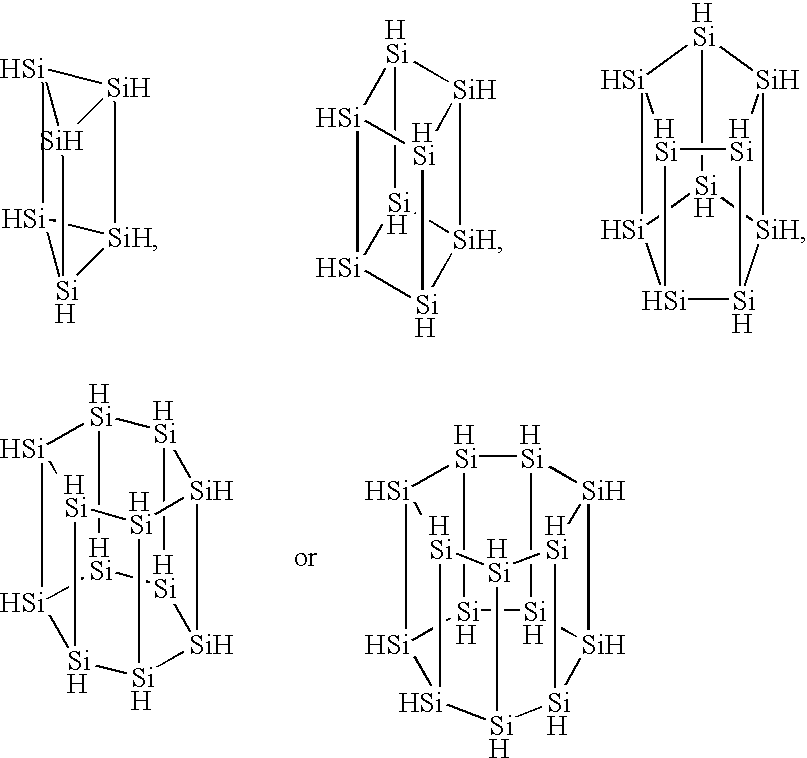
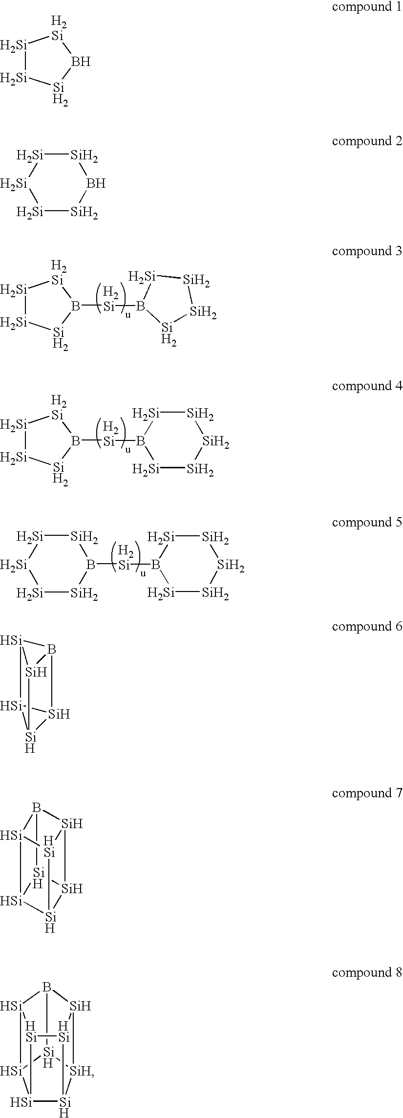
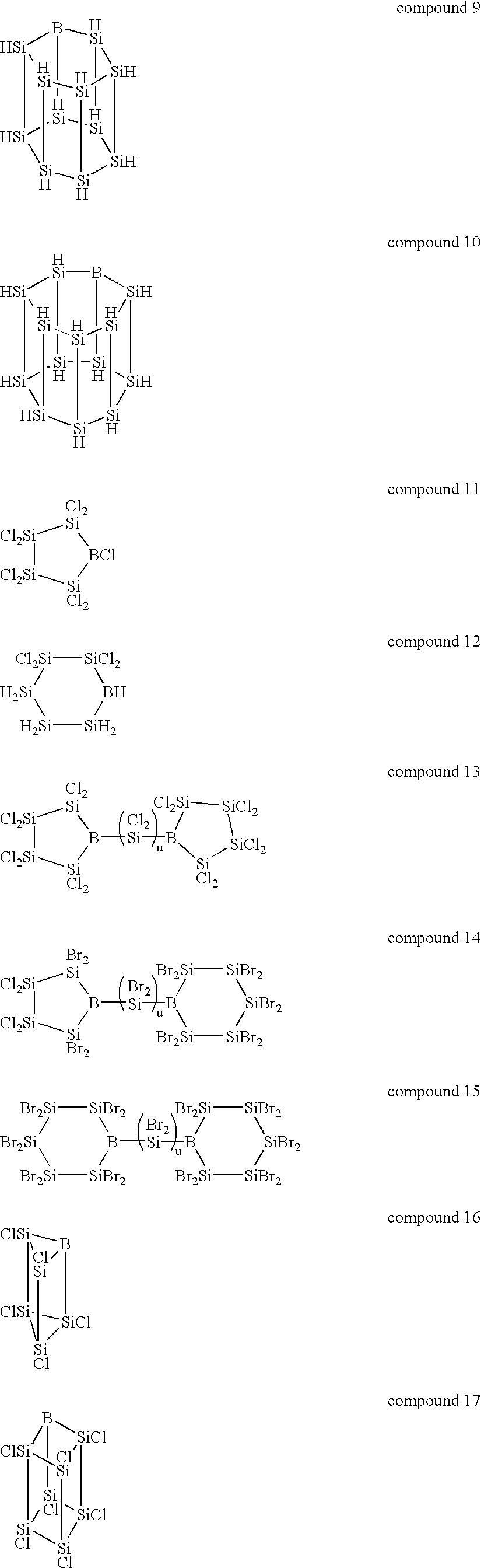
The inside of a 3-liter four-neck flask equipped with a thermometer, a condenser, a dropping funnel and an agitator was substituted with an argon gas, 2 liters of dried tetrahydrofuran and 75 g of metal lithium were charged into the flask, and the content of the flask was bubbled with an 20 argon gas. While this suspension was agitated at 0.degree. C., 500 g of phenyltrichlorosilane was added through the dropping funnel. The reaction was continued at 0.degree. C. until the metal lithium completely disappeared and, thereafter, the content of the flask was further agitated at room temperature 12 hours. The dark-brown reaction mixture was poured into ice water to precipitate the reaction product. This precipitate was separated by filtration, washed fully with water and vacuum dried to give 210 g of a light-yellow polycyclic silicon compound containing a phenyl group.

A hundred fifty grams of the phenyl group-containing polycyclic silicon compound obtained by the above...

Example

Synthesis Example 2

In the same manner of Synthesis Example 1, the inside of a 3-liter four-neck flask equipped with a thermometer, a condenser, a dropping funnel and an agitator was substituted with an argon gas, 2 liters of dried tetrahydrofuran and 63 g of metal lithium were charged into the flask, and the content of the flask was bubbled with an argon gas. While this suspension was agitated at -30.degree. C., a mixture of 253 g of diphenyldichlorosilane and 170 g of tetrachlorosilane was added through the dropping funnel. The reaction was continued until the metal lithium completely disappeared. Thereafter, the filtrate obtained by separating the unreacted lithium by filtration was poured into ice water to precipitate the reaction product. This precipitate was separated by filtration, washed fully with water and vacuum dried to give 210 g of a phenyl group-containing polycyclic silicon compound.

Two hundred and ten grams of the phenyl group-containing polycyclic silicon compound o...

Example

Example 3

A solution was prepared by dissolving 5 g of the hydrogenated polycyclic silicon compound obtained in Synthesis Example 2 in 10 g of toluene. This solution had a viscosity of 11 mPa.multidot.s. This solution was pattern-coated on a quartz substrate in an argon atmosphere by using an ink-jet head comprising a piezoelectric element. This substrate was dried at 150.degree. C. in an argon atmosphere and then thermally decomposed at 500.degree. C. to give a silicon film having a film thickness of 800 angstrom. When this silicon film was subjected to surface composition analysis by ESCA, only silicon atoms were detected. Further, when the crystallinity of this silicon film by the Raman spectrum was measured, it was 100% amorphous.


PUM

PropertyMeasurementUnit
Compositionaaaaaaaaaa
Areaaaaaaaaaaa

Abstract

A coating composition comprising a silicon compound represented by the following formula (1):wherein X1 is a hydrogen atom or a halogen atom, and n is an integer of 4 or more, on the proviso that n occurrences of X1 may be the same as or different from one another, or a modified silane compound represented by the following formula (2):wherein X2 is a hydrogen atom or a halogen atom, Y is a boron atom or a phosphorus atom, n is an integer of 3 or more, l is an integer of 1 or more, and m is an integer of n to 2n+3, on the proviso that m occurrences of X2 may be the same as or different from one another, and solvent thereof. This coating composition is suitably used in the production of a device for forming a silicon film or a boron- or phosphorous-doped silicon film on a substrate having a large area.

Description

This invention relates to a coating composition containing a specific silicon compound. More specifically, it relates to a coating composition containing an elementary silicon that has been imparted with excellent semiconducting properties by heat treatment or irradiation of light or a silicon compound that can be converted into a modified silicon film as used in LSI, thin-film transistor, photoelectric converter, photosensitive body and the like.PRIOR ARTSTo form an amorphous silicon film and a polysilicon film, thermal CVD (Chemical Vapor Deposition), plasma CVD, photo CVD or the like of a monosilane gas or a disilane gas has been used heretofore. In general, thermal CVD (refer to J. Vac. Sci. Technology., vol. 14, p.1,082(1977)) has been widely used for polysilicon, while plasma CVD (refer to Solid State Com., vol. 17, p.1,193(1975)) has been widely used for amorphous silicon, and they are used in the production of a liquid crystal display device that has a thin-film transistor a...

Claims


Application Information

Patent Timeline
IPC IPC(8): C01B33/00C01B33/04C01B33/08C08L1/00C08G77/00C08G77/60C09D183/16C09D1/00C09D183/00C23C18/12C23C18/00H01L21/28H01L21/02H01L21/205H01L21/288
CPCC09D1/00C09D5/24H01L21/02628H01L21/02532H01L21/02573H01L21/0242C09D7/20B05D3/065
Inventor MATSUKI, YASUO
Owner JSR CORPORATIOON
Why Eureka
Try Eureka