
Power scalable optical systems for generating, transporting, and delivering high power, high quality, laser beams

Inactive Publication Date: 2006-05-09
LOCKHEED MARTIN COHERENT TECH
View PDF14 Cites 50 Cited by
  • Summary
  • Abstract
  • Description
  • Claims
  • Application Information

AI Technical Summary

Benefits of technology

[0019]Another general object of this invention is to provide high power, diffraction limited, laser beams and amplifiers and waveguide systems that are capable of delivering such high power laser beams to one or more points of application without significant degradation of beam quality.
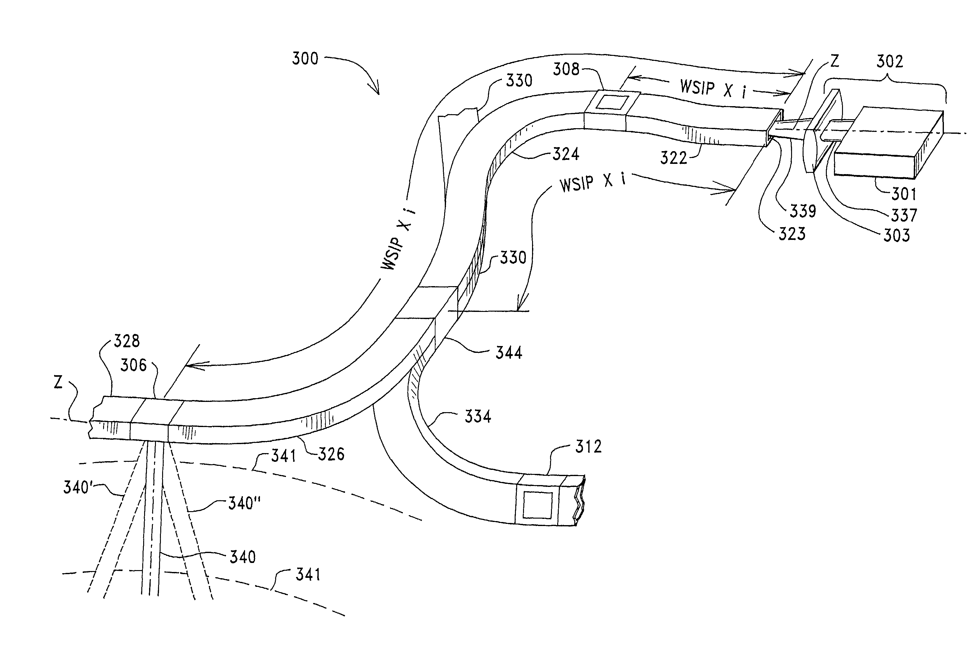
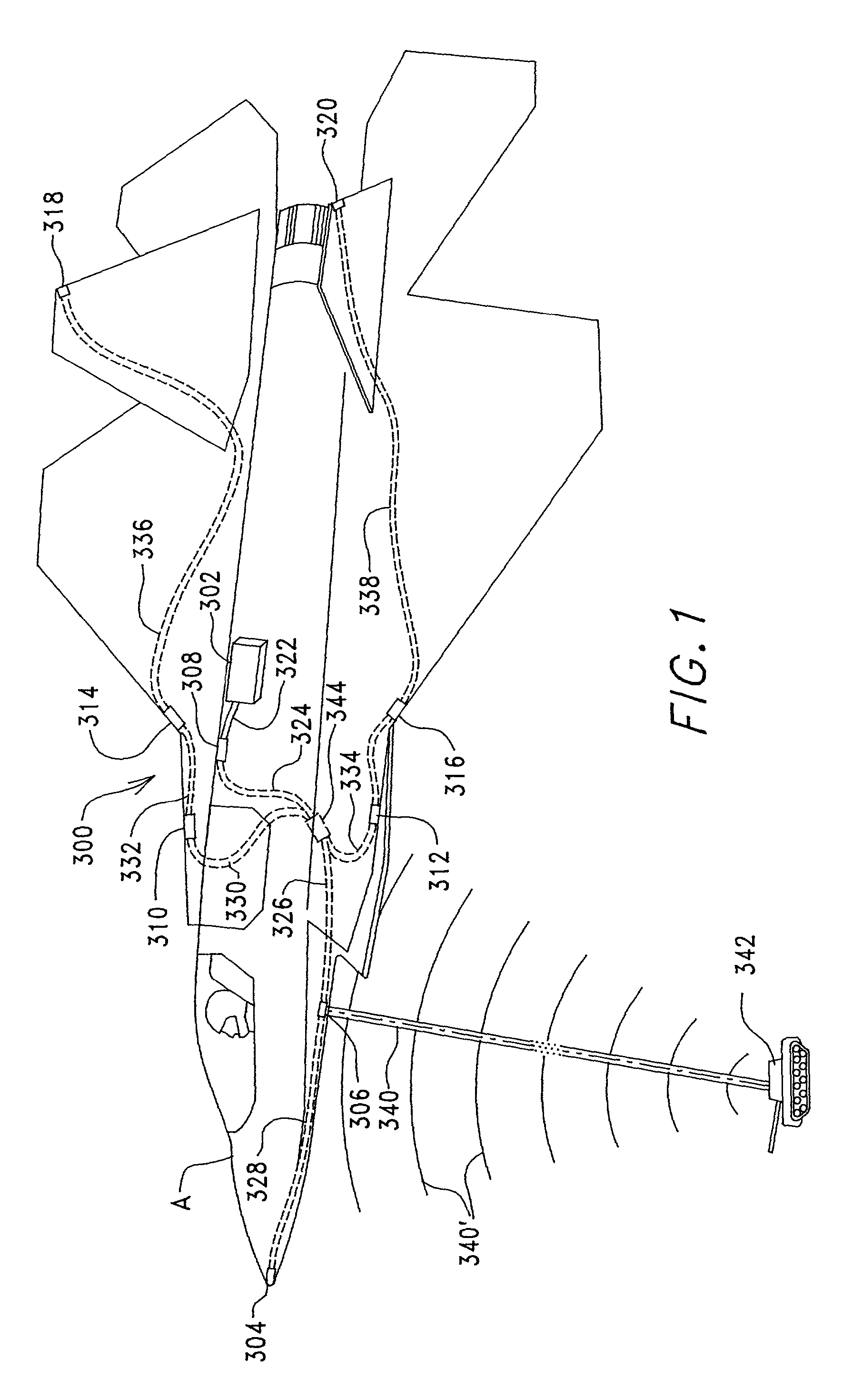
[0043]To further achieve the foregoing and other objects and, in accordance with purposes of the present invention, and as broadly embodied and described herein, a method of providing a high power, diffraction limited laser beam to a desired application comprises producing a high power beam with a desired spatial profile, coupling the beam into an elongated, multi-mode, self-imaging, transport waveguide that has a least one output aperture positioned at a self-imaging plane, and coupling the beam out of the output aperture for a desired application. According to one aspect of the invention, a high power laser beam can be produced by an advantageous combination of a rectangular (preferably one-dimensional), multi-mode, self-imaging, solid core, amplifier waveguide with a heat sink in thermally conductive contact with at least one, and preferably two, of the large aspect (waveguiding) sides of the waveguide. While this combination works with any desired beam profile, another advantageous addition to the combination, thus inventive feature, is to condition the beam to have a super-Gaussian (preferably a low order super-Gaussian) profile, which can enhance scalability to high power levels while delivering high quality, diffraction limited, beams. At the same time, the self-imaging feature of the waveguide, thus ability to use larger aperture waveguides, also facilitates scaling to high power levels, even though such larger aperture waveguides are multi-mode. Scaling to high power levels is also facilitated by the flat, thin, elongated, rectangular, cross-sectional profile of a rectangular (especially one-dimensional), multi-mode, self-imaging, waveguide core, which provides efficient heat dissipation from the core. Delivering the high power laser beam through an elongated, multi-mode, rectangular, self-imaging, transport waveguide (preferably, but not necessarily, hollow) can include twisting and / or bending the transport waveguide to route the outlet aperture to a desired position. Changing index of refraction of a window, such as a diffraction grating, liquid crystal, or other material at a re-imaging plane provides an outlet aperture for some or all of the beam with the desired spatial profile. A grating (preferably comprising numerous spaced-apart strips of the liquid crystal material) can direct or steer the beam. The output beam of one transport waveguide can be coupled into another multi-mode, rectangular, self-imaging, transport waveguide, or it can be combined with another, phase-matched, beam to produce an even higher power beam with the desired spatial profile.

Problems solved by technology

However, if there are several targets or objects close to each other, a long pulse will not allow the range detector to distinguish between light energy reflected from the several targets or objects, respectively, unless high bandwidth amplitude modulated (AM) or frequency modulated (FM) chirp is utilized.
Unfortunately, prior to this invention, typical adverse, non-linear and thermal effects, such as thermal self-focusing and self-phase modulation, stress birefringence, stimulated Rayleigh, Raman, and Brillouin scattering, intermodel dispersion, and the like, limit the amount of power that can be produced by current state-of-the-art waveguide resonators and amplifiers, such as those that use crystalline laser materials in the form of bulk rods or slabs pumped with laser diodes and non-crystalline materials such as glassy optical fibers.
However, at high powers, it is difficult to achieve both excellent pump / mode matching with high pump absorption and diffraction-limited beam quality.
Longitudinal pumping can result in excellent mode matching, but it is limited in power due to the thermal stress fracture limit, i.e., the medium will crack when it gets too hot [S. Tidwell et al., “Scaling CW Diode-End-Pumped Nd:YAG Lasers to high Average Powers,” IEEE J. Quantum Electron, vol.
Another common problem in state-of-the-art bulk laser geometries prior to this invention is thermal management—both in the form of heat extraction and dissipation as well as optical distortion due to thermal gradients.
The heat build-up results from absorption of high pump energy in a small volume of laser material, and active cooling in the form of bulky heat exchangers or refrigeration systems is usually required to remove the heat.
Such active cooling adds severely to the size, weight, and power requirements of the system.
Thermal gradients in the laser materials are manifested in the forms of undesirable thermal lensing or self-focusing, due to thermally-induced birefringence, which alters polarization of the light.
These problems are significant, because there is typically power dependent birefringence, which alters polarization, and bi-focusing, which degrades spatial and temporal coherence.
However, operation in quasi-three-level laser material (Yb, Er, Tm, Ho) severely exacerbates the thermal problem, since it requires much higher pumping to reach threshold and / or refrigerated cooling to depopulate the thermal laser level.
Consequently, there has not been any real solution to the thermal problems when scaling bulk laser materials to high power levels.
However, power scaling, i.e., scaling up to higher power levels, in such single-mode optical fibers is restricted by inability to make efficient coupling of pump light energy into the optical fiber and by the minute, single-mode core, (10–30 μm diameter) holey or photonic fibers and core cluster fibers, which can only handle so much light energy without overheating, distortion, or suffering catastrophic facet (coupling surface) failure.
However, drawbacks of such double-clad fiber designs for laser resonators and amplifiers include: (i) The pump light energy, while introduced into, and confined by, the core and inner cladding together, is absorbed only in the core region so that the effective absorption coefficient is reduced by approximately the ratio of the core area to the inner cladding area; (ii) The inner cladding size is still very small, even though larger than the core, so that coupling of a laser diode array into the inner cladding region is still quite difficult and not very efficient; and (iii) The outer cladding region must be made with a much lower index of refraction than the inner cladding for optical confinement of the pump light to the inner region, and such lower index of refraction materials are often polymers (plastic), which are much more susceptible to damage than glass, especially from heat.
Transporting such high-power, high-quality beams to points of application, such as the industrial cutting and materials processing, medical, laser radar ranging, imaging, and tracking applications mentioned above, can also present heretofore unsolved problems.
Consequently, it is often not possible to place high power laser beam production and amplifying equipment at the most effective launch locations in the airplane.
Yet, transport of high power, high quality laser beams without degradation of beam power, quality, temporal and spatial coherence, polarization, and the like presents serious problems with many of the same kinds of obstacles as described above for the beam production and amplification.
For example, single-mode waveguides, such as single-mode optical fibers, can maintain beam quality, but their very small size for single-mode operation severely limits power transport capabilities.
Single-mode waveguides, including fibers, are simply unable to handle that kind of optical power or light energy.
Multi-mode fibers and waveguides are larger than single-mode fibers and waveguides, thus can transport more power, but they do not maintain spatial coherence, polarization, and the like, because of multi-mode interference and other reasons mentioned above.
Free-space light transport has its own problems, not the least of which is that the light paths have to be unobstructed and alignment and stability problems in non-laboratory environments are extremely difficult to overcome and are often insurmountable.
Techniques have been previously developed to actively compensate for finite length circular fiber spatial mode deficiencies, including SBS phase conjugation, but these techniques are limited in scope to narrow spectral line width lasers to match the SBS gain bandwidth, enough optical power to provide the nonlinear drive field required, and wavefronts that are not fully reconstructed by phase conjugation.
If this index profile is disturbed, potentially as a result of high power operation, the polarization integrity may drift or be lost.
Beam quality issues may arise, for example, related to mode mixing as previously described, or with regard to “bend, buckle and twist” of the waveguide and potentially resulting modification of at least spatial coherence, wherein, for example, a twist of the waveguide could result in beam formation equivalent to a negative lens, and a bend in the waveguide may result in beam formation potentially equivalent to a positive lens.
Such applications of waveguide technology have not been adequately addressed in the past attempts previously described or in other previous beam transport technologies.

Method used


Image

  • Power scalable optical systems for generating, transporting, and delivering high power, high quality, laser beams
  • Power scalable optical systems for generating, transporting, and delivering high power, high quality, laser beams
  • Power scalable optical systems for generating, transporting, and delivering high power, high quality, laser beams

Examples


embodiment 70

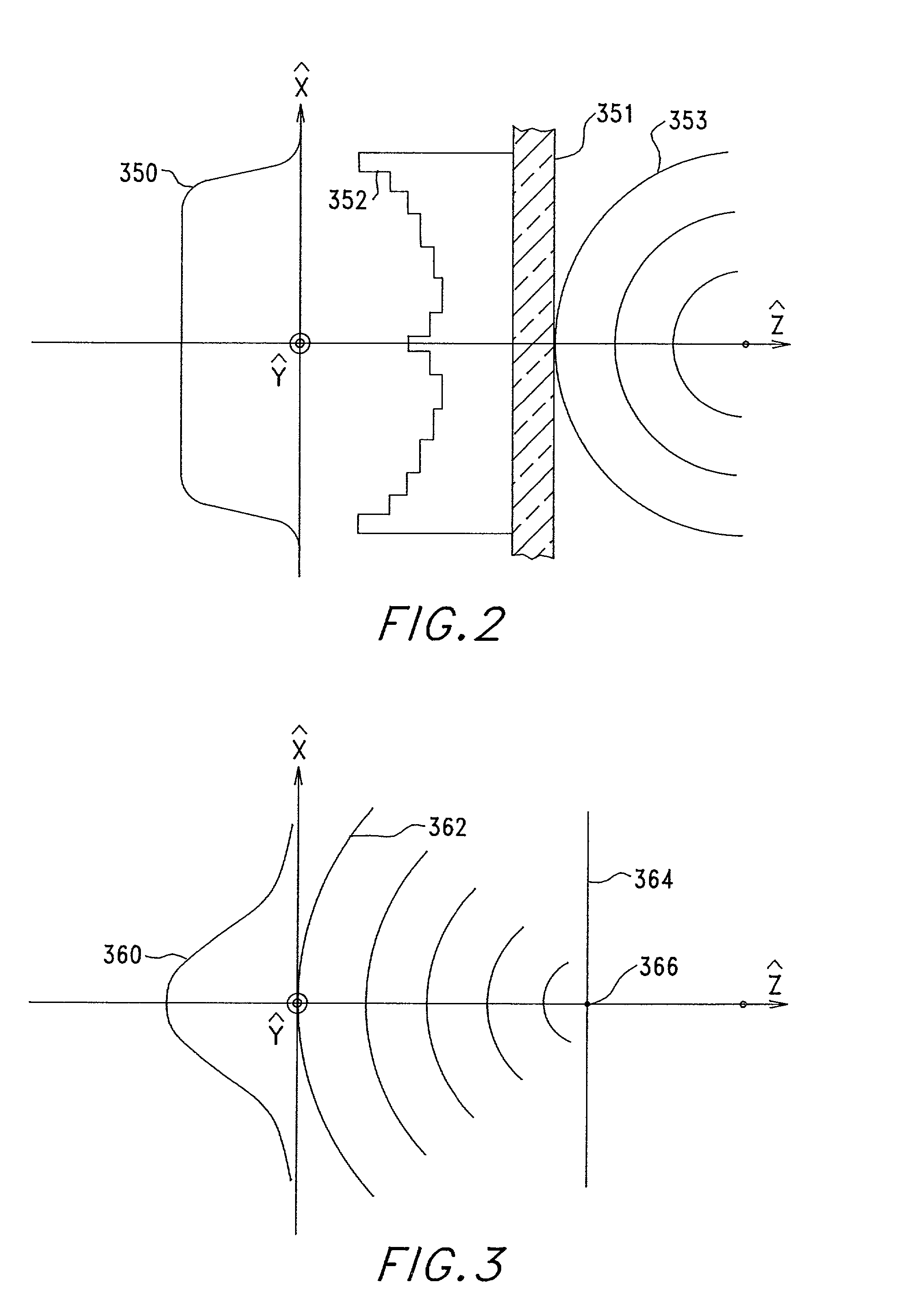
[0106]As explained above, spatially coherent, lower order super-Gaussian, beams are particularly desirable for the power scalable, rectangular, self-imaging, waveguide optical systems of this invention, because they can have more light energy than common TEM00 Gaussian beams of similar size, and they can be adapted to utilize more fully the rectangular cross-section of rectangular waveguides, especially one-dimensional rectangular waveguides. For example, waveguides with thicknesses in the range of 100 μm to 1 cm or more combined with a super-Gaussian beam can be scaled up to produce and / or transport the high power levels discussed above according to this invention. A preferred example very high peak power self-imaging waveguide according to this invention is a 1 cm×1 cm core with a lower order super-Gaussian beam. A spatially coherent, lower order super-Gaussian beam 12 for focusing on a rectangular input aperture 26, such as that shown in FIG. 4, can be provided by amplitude or ph...

embodiment 40

[0108]The high-power optical amplifier 10 of this invention shown in FIG. 4 and described above is one simple embodiment illustrating the use of a multi-mode, rectangular, re-imaging waveguide with a core comprising a gain or mixing medium for amplifying a light beam 12 or mixing with other beams. There are, of course, many other useful amplifier configurations and embodiments that will occur to persons skilled in the art, once they understand the principles of this invention. For example, as shown in FIG. 9, a double-pass optical amplifier embodiment 40, in which the light beam 42 being amplified is passed twice through the rectangular, multi-mode, self-imaging, waveguide 50 to thereby extract even more energy from the gain medium in the waveguide core 52. In this example, the gain medium that comprises the core 22, such as Nd:YAG, is pumped with light energy 64 with, for example, a laser diode 60 coupled into the core 22 by a lens focusing system 59, which focuses the light 64 pro...

embodiment 400

[0170]An alternate, grating window, embodiment 400 can be used in place of the window 380 in the sidewall launch aperture 306 to provide steering of the output beam 340, as illustrated diagrammatically in FIG. 1, and as 340′ and 340″ in FIGS. 24a–c. With initial reference to FIG. 24, a small portion of a grating window 400 is shown in an enlarged cross-section. Essentially, the grating window 400 can be any diffraction outcoupler embodiment, as explained above, but in a grating format. Fixed and programmable diffractive incouplers / outcouplers can be achieved via processes, such as (i) liquid crystals; (ii) semiconductor gratings—either etched or electrically programmable; (iii) photorefractive gratings—either electrically or optically written; (iv) photochromic and / or electrochromic gratings; or (v) etched relief gratings. Moreover, the diffractive grating structure can be curved, linear, chirped, or any combination of these features.

[0171]An example grating window 400 is similar to...


PUM


Abstract

Power scalable, rectangular, multi-mode, self-imaging, waveguide technologies are used with various combination of large aperture configurations, 20, 50, 80, 322, 324, 326, 328, 330, 332, 334, 336, 338, Gaussian 360 and super-Gaussian 350 beam profiles, thermal management configurations 100, flared 240 and tapered 161 waveguide shapes, axial or zig-zag light propagation paths, diffractive wall couplers 304, 306, 308, 310, 312, 314, 316, 318, 320 and phase controller 200, flexibility 210, phased arrays 450, 490, beam combiners 530, 530′, and separators 344, 430, and other features to generate, transport, and deliver high power laser beams.

Description

CROSS-REFERENCES TO RELATED APPLICATIONS[0001]This patent application is a continuation-in-part of U.S. patent application Ser. No. 09 / 968,974, filed on Oct. 1, 2001 now U.S. Pat. No. 6,894,828, which is incorporated herein by reference and claims the benefit of U.S. provisional patent application No. 60 / 259,681, filed on Jan. 4, 2001.CONTRACTUAL ORIGIN OF THE INVENTION[0002]The United States Government has rights in this invention under Contract No. N68335-00-C-0486 between the United States Department of Defense and Coherent Technologies, Inc., and certain Air Force contracts.TECHNICAL FIELD[0003]This invention is related generally to laser beam generation, amplification, and delivery systems and, more specifically, to power scalable optical systems for high power laser radar (ladar) applications, such as long-range targeting, imaging, and other applications, and includes light beam amplifiers, laser devices, waveguide technologies, and optical coupling, switching, and beam steeri...

Claims


Application Information

Patent Timeline
IPC IPC(8): H01S3/00G02B6/26H01S3/042H01S3/063H01S3/0941H01S3/16H01S3/23H01S5/10H01S5/50
CPCG02B6/032H01S3/063G02B6/2813H01S3/042H01S3/08095H01S5/50H01S3/0941H01S3/1643H01S3/2333H01S3/2383H01S5/10H01S3/094057
Inventor SMITH, DUANE D.PELOUCH, WAYNE S.PRASAD, NARASIMHA S.UNTERNAHRER, JOSEFKOROSHETZ, JOHNMCKINNIE, IAIN
Owner LOCKHEED MARTIN COHERENT TECH
Learn More