

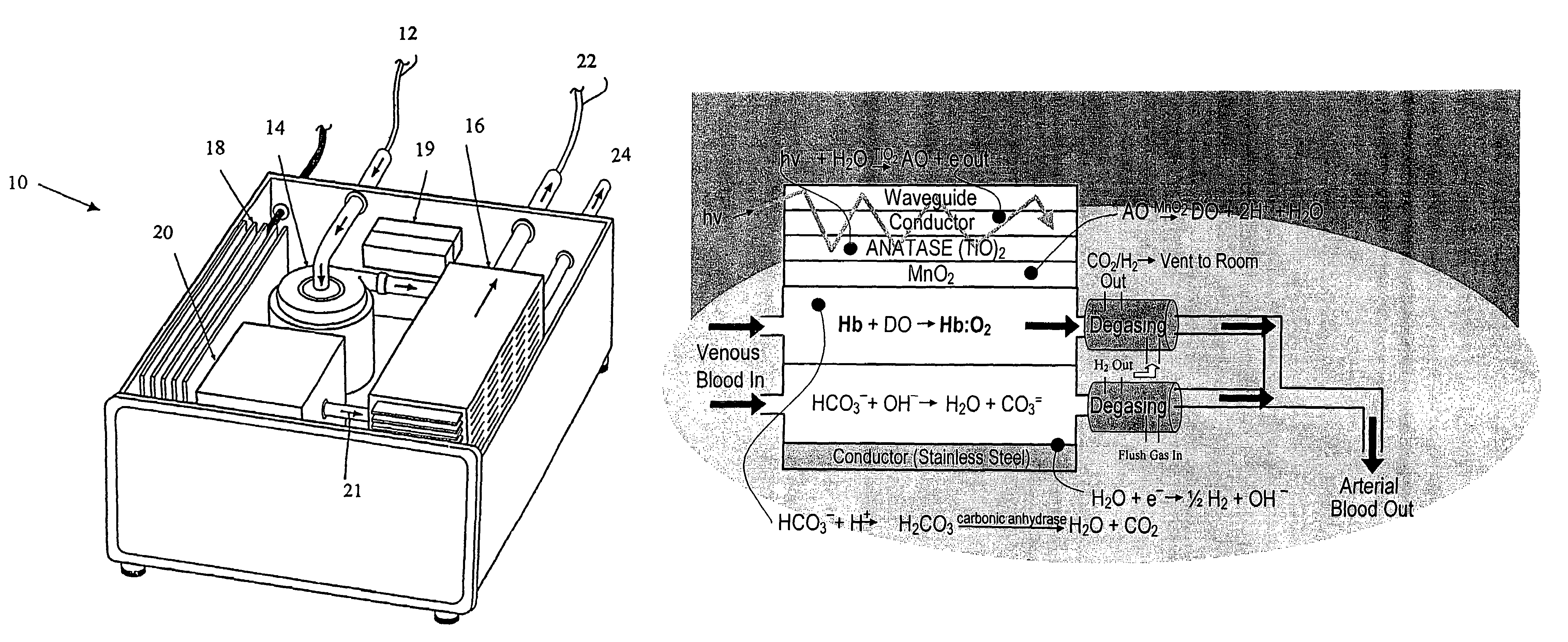
Photolytic cell for providing physiological gas exchange
a photolytic cell and gas exchange technology, applied in the field of photolytic cells, can solve the problems of insufficient knowledge of pulmonary pathophysiology, lack of emerging therapies, and no new innovative respiratory assist therapy for patients with severe, life-threatening lung diseases, and achieve the effects of controlling the commercial value of the technology, small size and low cos
- Summary
- Abstract
- Description
- Claims
- Application Information
AI Technical Summary
Benefits of technology
Problems solved by technology
Method used
Image

Examples
example 1
[0237]A prototype photolytic artificial lung was produced in order to demonstrate the ability of the device and accompanying processes to re-oxygenate synthetic blood serum (Locke's Ringer Solution), with concomitant CO2 removal and pH control, using thin film constructs. In this regard, a photolytic test flow cell (see FIG. 3) was constructed using exemplar materials for the elements of the photolytic artificial lung—a conductive coating of vacuum deposited Ti metal, a coating of adherent TiO2 (anatase), a MnO2 particulate layer, and then a bicarbonate solution. A U.V. laser light was introduced to the transparent glass or quartz substrate. This cell was used to collect pH and cell electrical current data as a function of laser U.V. irradiation. The details of the construction of such a prototype and the results produced thereby are discussed below.
[0238]In this regard, a photolytic test flow cell as shown in FIG. 3 of the photolytic artificial lung was prepared. Specifically, amon...
example 2
[0273]To demonstrate the ability of the photolytic reaction sequence to generate DO, two Hansatech batch reactors were set up, one for liquid phase (DO), and one for gas phase oxygen (PO2) detection. Both gas tight reactors were fitted with an oxygen membrane sensor and a window for illumination. These reactors were designed to allow quantitative assessments of oxygen production and quantum yields. Although, the results verify that DO can be produced photolytically from water, and that O2 can be produced from AO using a thin film catalyst.
[0274]The critical step of photolytically producing DO from H2O was illustrated in the liquid phase cell using a slurry of the anatase titania (TiO2) photon absorber and dissolved ferric ion at pH 1.9 as an electron absorber. While not intended to be used in the final device, the use of ferric ions here allows the tests to be run within the setting of the electrically isolated cell, in which the ferric ions are maintained in solution by the relativ...
example 3
[0277]A test cell was created to determine the extent to which the indicated chemical conversions occurred only during illumination, and in association with the active surface material. FIG. 3 is a diagram of the flow cell constructed with the essential elements of design, a conductive coating of vacuum deposited Ti metal, a coating of adherent TiO2 (anatase) and a MnO2 particulate layer. UV laser light was introduced to irradiate transparent glass or quartz substrate. This cell was used to collect pH, electrical current, dissolved oxygen, and gas phase CO2 data as a function of laser irradiation.
Synthesis of Photoactive Layers
[0278]The photoactive constructs consisted of a glass substrate, a conducting layer, and a photoactive layer. The glass substrates were 25 mm×9 mm in size, and 98% transmissive at the desired wavelength. The (Ti) conductive layer(s) were laid down on the glass surface using a vacuum sputter coating procedure. In order to validate the efficiency of Ti, various ...
PUM
| Property | Measurement | Unit |
|---|---|---|
| gas transfer surface area | aaaaa | aaaaa |
| thickness | aaaaa | aaaaa |
| diffusion distance | aaaaa | aaaaa |
Abstract
Description
Claims
Application Information