A method for manufacturing a quantum dot-doped solar fluorescent concentrating power generation system

A technology of a power generation system and a manufacturing method, applied in the field of solar power generation, can solve the problems of shortening the service life of solar cells, limiting commercialization, self-absorption of poor energy, etc. Effect

Active Publication Date: 2018-06-05
孙小卫 +1
View PDF10 Cites 0 Cited by
  • Summary
  • Abstract
  • Description
  • Claims
  • Application Information

AI Technical Summary

Problems solved by technology

[0007] However, there are still many limitations in the invention technology of existing solar fluorescent concentrators
In the selection of fluorescent materials, the common technology proposes to use organic dyes as fluorescent materials. However, organic dyes are easy to decompose under the irradiation of sunlight for a long time, have poor light and thermal stability and serious energy self-absorption loss; some technologies also propose to use inorganic quantum dyes. Dots (QDs) cadmium sulfide, cadmium selenide, lead sulfide, or mercury cadmium telluride, or any combination thereof, are used as fluorescent materials. This type of quantum dot material contains toxic ions such as heavy metals, which seriously pollutes the environment and severely limits its commercialization. to promote
[0008] In addition, there is also a technology that proposes to install the solar cell on a large-area fluorescent light-receiving surface and directly expose it to sunlight. Since nearly 40% of the infrared light without photoelectric effect in sunlight will be focused on the solar cell, resulting in solar cell Working in a high-temperature environment for a long time, coupled with the aging effect of high-energy ultraviolet rays, the service life of solar cells is greatly shortened; at the same time, the light-absorbing and opaque characteristics of the solar cells themselves prevent light from penetrating the solar cells and are blocked from entering the building Indoor, thus limiting the application of the power generation system on the curtain wall or roof of the building group

Method used


Image

  • A method for manufacturing a quantum dot-doped solar fluorescent concentrating power generation system
  • A method for manufacturing a quantum dot-doped solar fluorescent concentrating power generation system
  • A method for manufacturing a quantum dot-doped solar fluorescent concentrating power generation system

Examples


Embodiment 1

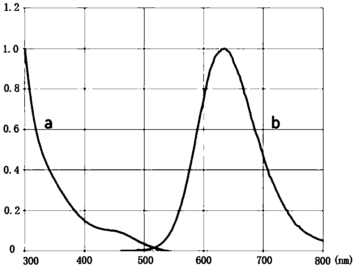
[0037] Inorganic nano-CuInS is selected as fluorescent material 2 (CIS) quantum dots, the required CIS quantum dots are synthesized through the "one-pot reaction method". The outer layer of the CIS quantum dots is covered with a layer of ZnS. Absorbed blue-violet light is converted to broadband red-orange light emission. The synthesized CIS quantum dots are dispersed in n-hexane solution for use, and its characteristic spectrum is as follows figure 1 As shown, a is the absorption spectrum, b is the emission spectrum, and the wavelength difference between the excitation wavelength and the emission wavelength is greater than 180nm.

[0038] The planar optical waveguide is made by bulk polymerization of methyl methacrylate. The specific polymerization process is as follows:

[0039] Measure 20mL of the bulk solution of methyl methacrylate in a conical flask, weigh the white solid of azobisisobutyronitrile and add it to the bulk solution of methyl methacrylate, stir it evenly wi...

Embodiment 2

[0045] Inorganic nano AgInSe is used as fluorescent material 2 Quantum dots, the required AgInSe was synthesized by "one-pot reaction method" 2 Quantum dots, AgInSe 2 The outer layer of quantum dots is wrapped with a layer of ZnSe, and the synthesized AgInSe 2 Quantum dots have the characteristics of broadband blue-violet light absorption and high quantum yield, and can convert the absorbed blue-violet light into broadband red-orange light emission. The synthesized AgInSe 2 Quantum dots are dispersed in n-hexane solution for use.

[0046] The planar fluorescent optical waveguide is manufactured by using polymethyl methacrylate solid particles and fluorescent material powder through physical mixing and high-temperature pressing molding. The specific process is: make fluorescent material into powder, weigh appropriate amount of polymethyl methacrylate solid particles and powdery fluorescent material, mix them uniformly by physical blending method, then transfer them to a spec...

Embodiment 3

[0049] The fluorescent material is inorganic nano CuInTe 2 Quantum dots, the desired CuInTe was synthesized by a "one-pot reaction method" 2 Quantum dots, CuInTe 2 The outer layer of quantum dots is wrapped with a layer of ZnTe, and the synthesized CuInTe 2 Quantum dots have the characteristics of broadband blue-violet light absorption and high quantum yield, and can convert the absorbed blue-violet light into broadband red-orange light emission. The synthesized CuInTe 2 Quantum dots are dispersed in n-hexane solution for use.

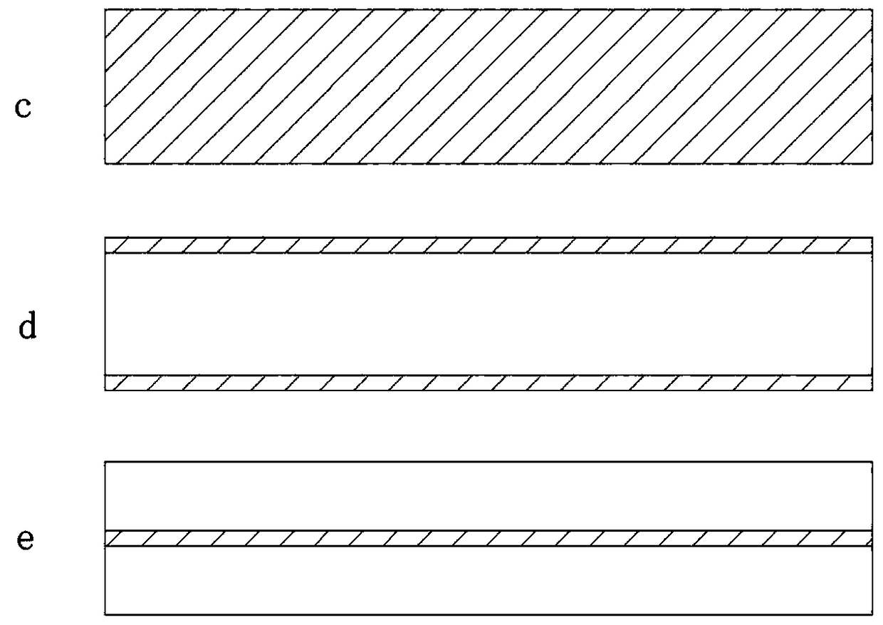
[0050] The planar optical waveguide uses polycarbonate as the matrix, and the upper and lower surface areas of the planar optical waveguide are 10 times the area of ​​its side surfaces. The fluorescent material is sprayed to form a fluorescent film on the upper and lower surfaces of the planar optical waveguide. The composite method is as follows: figure 2 As shown in d, a planar fluorescent lightguide is obtained. The specific process is: uniform...


PUM


Abstract

The invention belongs to the technical field of solar power generation, and discloses a solar fluorescent focusing power generation system of a quantum dot doped type, and a manufacturing method therefor. The system comprises a plane fluorescent optical waveguide and a solar cell, wherein the plane fluorescent optical waveguide is formed by the combination of a fluorescent material and a plane optical waveguide. The fluorescent material is a three (or more)-element inorganic quantum dot material, and the chemical composition of the fluorescent material is AInB2, wherein A is one or the combination of Cu and Ag, B is one or the combination of S, Se and Te. Through employing the environment-friendly type quantum dot fluorescent material which is good in optical stability and high in efficiency to be combined with the technology of plane optical waveguide and the solar cell, the novel system is constructed, is embedded in a curtain wall of a building group or at a top of a house, and achieves the integration of photovoltaic power generation and a building.

Description

technical field [0001] The invention belongs to the technical field of solar power generation, and relates to a solar fluorescent concentrating power generation system and a manufacturing method thereof, in particular to a quantum dot-doped solar fluorescent concentrating power generation system and a manufacturing method thereof. Background technique [0002] With the excessive development and use of natural resources such as coal, oil and natural gas in the world, the emission of a large amount of exhaust gas makes the global climate warming rapidly and the environment is deteriorating day by day. In response to the national strategic policy of energy conservation and emission reduction, my country is increasing its efforts in the development of various renewable energy sources. Solar energy has become one of many renewable energy sources due to its inexhaustible, green, low cost, and convenience features. Key development targets in energy. [0003] Although solar power ge...

Claims


Application Information

Patent Timeline
Patent Type & Authority Patents(China)
IPC IPC(8): H02S40/20G02B6/00
CPCY02B10/10Y02E10/50
Inventor 王恺李臣陈威郝俊杰秦静
Owner 孙小卫
Why Eureka
Try Eureka