Conversion reaction-based magnesium battery with high energy density

A high energy density, magnesium battery technology, applied in battery electrodes, secondary batteries, circuits, etc., can solve the problems of limited lithium ion concentration, inability to drive conversion reactions, limited battery specific capacity, etc., to improve cycle performance and safety. performance, avoiding the hidden danger of battery short circuit, and broadening the selection range

Active Publication Date: 2017-03-22
SHANGHAI INST OF CERAMIC CHEM & TECH CHINESE ACAD OF SCI
View PDF6 Cites 15 Cited by
  • Summary
  • Abstract
  • Description
  • Claims
  • Application Information

AI Technical Summary

Problems solved by technology

However, the positive electrode reaction of the dual-salt system magnesium battery reported so far is still limited to the embedded frame material, the electron transfer does not exceed one electron, and the energy density does not exceed 300Wh / kg, which still cannot meet the development needs of mobile devices.
For example CN104538669A discloses a kind of rechargeable magnesium battery, its anode material is titanium dioxide, electrolytic solution is magnesium borohydride and lithium borohydride dissolved in organic ether, and anode material is metallic magnesium or magnesium alloy, but this anode reaction is based on ion intercalation reaction , only single-electron transfer occurs, so the energy density is very limited (about 135Wh / kg)
CN102460796A discloses a magnesium battery, the anode material of which is FeS 2 etc., the electrolyte contains magnesium perchlorate and lithium hexafluorophosphate (magnesium-lithium double salt), etc., and the negative electrode material is metal magnesium or magnesium alloy, but the electrolyte is easy to cause passivation of the Mg negative electrode, and is mainly used for primary batteries rather than rechargeable batteries; and Lithium hexafluorophosphate is only used as an additive to the electrolyte, and the amount added is only 0.5% by weight. Limited by the concentration of lithium ions, it cannot drive a complete conversion reaction, and the specific capacity of the battery (382mAh / g) is limited.

Method used


Image

  • Conversion reaction-based magnesium battery with high energy density
  • Conversion reaction-based magnesium battery with high energy density
  • Conversion reaction-based magnesium battery with high energy density

Examples


preparation example Construction

[0034] The manufacturing method of the magnesium battery of this invention is demonstrated below.

[0035] Preparation of the positive electrode: In one example, after uniformly mixing at least one of the above-mentioned positive electrode materials (such as commercial fluoride or sulfide), conductive carbon material, binder, and solvent, coat it on the current collector, and dry it. A positive electrode for a magnesium battery is prepared. The mass ratio of the positive electrode material, the conductive carbon material and the binder may be 8:1:1, 7:2:1 or 6:2:2. Conductive carbon materials include, but are not limited to, Super P, carbon black, and the like. Binders include, but are not limited to, polyvinylidene fluoride (PVDF), polytetrafluoroethylene (PTFE), sodium carboxymethylcellulose (CMC), and the like. Solvents include, but are not limited to, N-methylpyrrolidone (NMP), tetrahydrofuran (THF), and the like. Current collectors include, but are not limited to, carb...

Embodiment 1

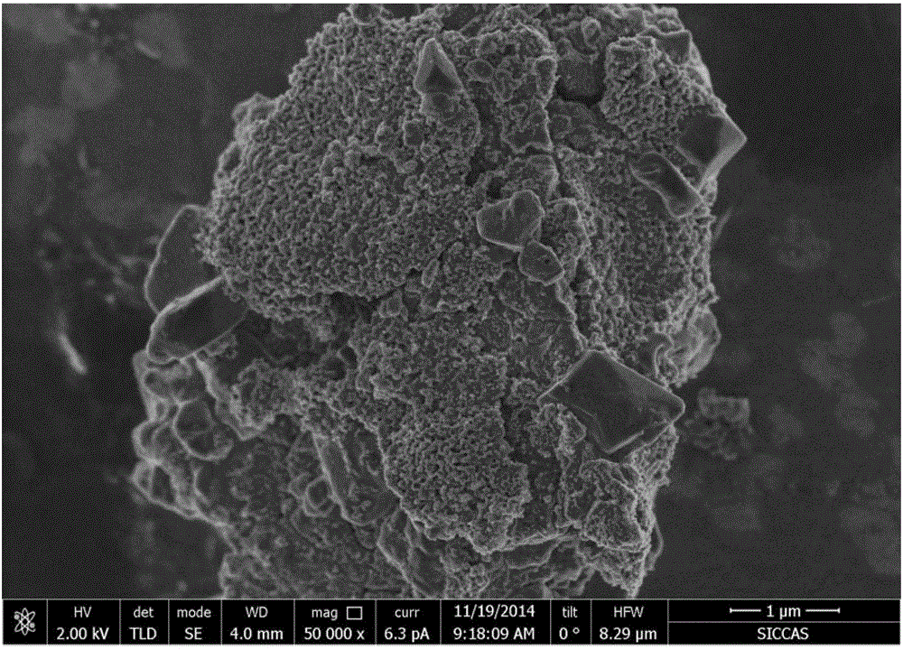
[0041] 1) FeS 2 Preparation of cathode materials

[0042] Weigh commercial FeS 2 Powder sample 24mg, Super P 6.8mg, put into the mortar and grind for 30min. Then add 68 μl of PVDF and NMP solutions with a concentration of 20 mg / μl, grind and stir for 10 to 15 minutes. Spread the black paste evenly on 12 pieces with an area of ​​50mm 2 carbon paper and dried in a vacuum oven at 80°C for 12 hours. The carbon paper loaded with the active substance after vacuum drying was weighed again, and packed into a glove box.

[0043] 2) Preparation of lithium-magnesium double-salt electrolyte

[0044] Put lithium borohydride and magnesium borohydride into an argon glove box. Add 327mg of lithium borohydride and 54mg of magnesium borohydride into 10ml of diethylene glycol dimethyl ether solvent, and magnetically stir for 24 hours to fully dissolve the solute.

[0045] 3) Battery assembly and testing

[0046] The 2025 button battery was assembled in an argon glove box with water value...

Embodiment 2

[0048] 1) Preparation of FeS cathode material

[0049] Weigh 24 mg of FeS powder sample and 6.8 mg of Super P, and grind them in a mortar for 30 min. Then add 68 μl of PVDF and NMP solutions with a concentration of 20 mg / μl, grind and stir for 10 to 15 minutes. Spread the black paste evenly on 12 pieces with an area of ​​50mm 2 carbon paper and dried in a vacuum oven at 80°C for 12 hours. The carbon paper loaded with the active substance after vacuum drying was weighed again, and packed into a glove box.

[0050] 2) Preparation of lithium-magnesium double-salt electrolyte

[0051] Put lithium borohydride and magnesium borohydride into an argon glove box. Add 327mg of lithium borohydride and 54mg of magnesium borohydride into 10ml of diethylene glycol dimethyl ether solvent, and magnetically stir for 24 hours to fully dissolve the solute.

[0052] 3) Battery assembly and testing

[0053] The 2025 button battery was assembled in an argon glove box with water value and oxyg...


PUM


Abstract

The invention relates to a conversion reaction-based magnesium battery with high energy density. A transition metal sulfide and/or a transition metal fluoride is used as a positive electrode material, a magnesium-lithium dual-salt solution is used as a non-aqueous electrolyte, and metal magnesium or magnesium alloy is used as a negative electrode. In the magnesium battery, the transition metal fluoride or the transition metal sulfide is used as the positive electrode material of such as magnesium-lithium hybrid battery system, the conversion reaction of the positive electrode material can be easily driven by lithium ions during the charge-discharge process, meanwhile, multi-electron conversion is achieved at a positive electrode and the negative electrode, the energy density of the positive electrode of the battery is improved to about 400 Wh/kg to the highest extent, and an energy density value can be comparable with that of a current lithium ion battery.

Description

technical field [0001] The invention belongs to the technical field of new energy, and in particular relates to the design of a magnesium battery system with high energy density based on the transformation reaction of transition metal sulfide or transition metal fluoride. Background technique [0002] From mobile phones to laptops to electric vehicles, mobile devices are playing an increasingly important role in people's daily lives, and the development of energy storage units for mobile devices will determine their status in the future human society. In addition to having high energy density, being able to work in a wide temperature range, and being environmentally friendly, future energy storage units should also have low raw material and processing costs for wide-scale promotion. As far as the current situation is concerned, lithium-ion batteries are the closest practical and commercial energy storage technology, but their production costs are high and there are safety ha...

Claims


Application Information

Patent Timeline
Patent Type & Authority Applications(China)
IPC IPC(8): H01M10/054H01M10/0563H01M4/58H01M4/46
CPCH01M4/46H01M4/466H01M4/58H01M4/5815H01M4/582H01M10/054H01M10/0563Y02E60/10
Inventor 李驰麟章也谢俊杰韩延林
Owner SHANGHAI INST OF CERAMIC CHEM & TECH CHINESE ACAD OF SCI
Why Eureka
Try Eureka