Cartilage repair plug

a cartilage repair and plug technology, applied in the field of cartilage repair plugs, can solve the problems of cartilage trauma, deterioration of previously damaged cartilage, and surrounding knees, elbows, shoulders, etc., to improve the anchorability of plugs, prevent them from coming loose, and increase the height-to-diameter ratio

Inactive Publication Date: 2001-11-08
ABS
View PDF0 Cites 393 Cited by
  • Summary
  • Abstract
  • Description
  • Claims
  • Application Information

AI Technical Summary

Benefits of technology

0103] It has been found that, in general, disk-shaped and cylindrical cartilage replacement plugs are the easiest to mold and have been found to be best suited for use in the repair of small to medium sized defects which are effectively repaired using a single plug. It has additionally been found that plugs with tapered sides or obliquely configured plugs have the best adhesion to the walls of the surrounding void cavity into which the plugs are implanted. Generally, the deeper the plug and the higher the height-to-diameter ratio, the better the plug remains in place in the void cavity. Flatter, shallower, disk-shaped plugs have a greater chance of becoming loose in the cavity.
0104] In order to improve the anchorability of plugs and prevent them from coming loose, the cartilage replacement plugs of the present invention may also have additional features to help anchor them to adjacent cartilage and / or adjacent plugs so as to hold them in place within the void cavity into which they are implanted. These additional features include ridges that are formed on the side surfaces of the plugs. The ridges may be discretely situated at various points on the sides of the plugs, or they may form a continuous band spirally wound around the side surface of the plug, or forming a series of separate, discrete, parallel bands around the side of the plug. FIG. 4 illustrates a plug 34 having a series of parallel ridges extending about its hexagonal periphery. The cross-sectional view (FIG. 5) shows that the ridges 36 have a barbed configuration wherein the distal side 38 of each ridge is gently sloped while the proximal side 40 has a steeper angle, which in this embodiment is substantially perpendicular to the side 42 of the plug. FIG. 6 illustrates the cross-section of another embodiment wherein the ridges 44 comprise ribs that have similarly sloped distal 46 and proximal 48 sides. FIG. 7 illustrates yet another alternative embodiment 50, wherein the ridges 52 comprise a single helix that spirals about the periphery of the plug. Ridges maybe formed on any of the plug configurations of the present invention, including configurations having circular or polygonal cross-sections or with tapered side surfaces or oblique end surfaces.

Problems solved by technology

Younger persons, ranging in age from children to young adults, often engage extensively in rigorous athletic activities, such as skiing, surfing, football, basketball, and even roller blading, which frequently results in accidents which cause traumatic injury to cartilage, particularly that surrounding the knees, elbows, and shoulders.
Osteoarthritis may also set-in following a traumatic injury to cartilage which is not repaired or is repaired improperly, leading to a further deterioration of the previously damaged cartilage.
When the defect is caused by traumatic injury and is extensive enough in size to involve a large mass of cartilage, the damage is not capable of self-healing.
Heretofore it was not possible to repair extensive cartilage defects.
Cartilage which has become defective through damage caused by traumatic injury from accident, whether sports related or from other causes, such as an automobile accident, as well as cartilage which has become defective as a result of deterioration due to the spread of a chronic degenerative disease, also typically gives rise to and is accompanied by severe pain, especially where the sites of the damage or disease is proximal to or constitutes part of an articulating joint surface, such as the knee.
The damaged or diseased portion of the cartilage is usually also accompanied by swelling of the surrounding tissue; and, where an articulating joint is involved, a disruption in the flow of lubricating synovial fluid around the joint often occurs, which, in addition to being a cause of the source of pain, usually leads to further mechanical abrasion, wear, and deterioration of the cartilage itself, finally resulting in the onset of osteoarthritis and complete disablement of the articulating joint, ultimately requiring complete replacement of the joint.
In the case of very young patients, however, complete replacement of a joint is problematic in that the patient's overall skeletal bone structure is not yet fully developed and is still growing, so that the replaced joint may actually be outgrown and no longer be of appropriate size for the patient when their fully matured adult size, stature, and skeletal structure is attained.
Moreover, in the past, many replacement knee, elbow joints and shoulder joints have typically had a maximum active useful life of only about ten years, due to wear and tear and erosion of the articulating surfaces of the joint with repetitive use over time, thereby necessitating periodic invasive surgery to replace the entire joint.
There are, however, several major problems and disadvantages associated with all of the various prior art cartilage replacement devices and methods which have heretofore been proposed.
The use of naturally derived cartilage plugs presents the major problems of lack of availability, limitations on the size of the repair that can be effected, and high potential for infection and transmission of disease.
Where the portion of damaged or diseased cartilage that is to be replaced is more extensive, however, such a self-harvesting procedure is not feasible because a sufficiently large plug cannot be extracted from another site without causing damage to or a weakening of the cartilage and underlying bone at the place of harvesting, or when being harvested from a site at or near another articulating joint, without causing damage to the operability of the articulating joint itself at the point of harvesting.
Moreover, there are a limited number of suitable locations on the body from which cartilage can be extracted for use elsewhere.
Depending on the age and overall health of the patient, as well as on other considerations, it may not be feasible to perform both procedures at the same time.
Such a dual procedure is time consuming and costly, and may be objected to on cost grounds in some insurance or managed care contexts.
Because the procedures are invasive, there is the additional risk of infection and pain to the patient occasioned by the need for two separate surgical procedures, at the cartilage harvesting site and at the cartilage repair emplacement site.
This alternative, however, also presents the same problems of limited sources of availability and potential for infection or transmission of disease.
In cases where it is necessary to reset larger portions of damaged or diseased cartilage from a patient, although procedures utilizing natural cartilage replacement plugs derived from cadaveric sources are not limited by considerations as to the amount of cartilage that can be excised from a particular location in order to preclude damage to or a weakening of the remaining cartilage and / or the joint, at the donor site, as occurs in a self-harvesting situation, there are still limitations as to the total amount of suitable cartilage that can be harvested from cadaveric sources, and the overall reliability of obtaining acceptable cadaveric cartilage sources at all is not high.
Some of the obstacles to this latter method involve the selection of one or more appropriate growth factors; the selection of appropriate delivery vehicles for controlled, time-release of the growth factors to ensure that the proper concentration of growth factor is maintained at the implant site; and necrosis of immature or newly regenerated tissue under stress or when subjected to loading conditions.
The principal disadvantages of this method are that it is very complicated and time consuming, requiring up to several months to fully culture the cartilage cells to the point where they are available for use in a preformed shape.
This method also faces the obstacles facing all such long-term methods mentioned above.
For example, the use of collagen sponges has been proposed as an implant to promote cartilaginous tissue ingrowth, however, this method has not demonstrated good long-term success.
From a practical viewpoint, these methods are limited to those applications where the surrounding cartilage forms a natural cartilage capsule that is capable to acting as a mold to contain and shape the injected liquid composition until it sets.
A major disadvantage of using reactive polyurethane-based systems is that residue diisocyanate in the reactant becomes hydrolyzed in the presence of moisture, to diamine, which is both toxic and carcinogenic.
A disadvantage associated with such approach is inherent in the lack of any physical anchoring to the underlying bone.
A disadvantage and limitation of this method and this type of cartilage replacement device is that it requires cell ingrowth into the felted backing for biologic fixation of the device.
This type of soft tissue fixation is less desirable than fixation achieved by bone ingrowth or fixation directly with bone without a fibrous tissue interface.
Their device is composed of a layer of polymer attached to a porous felt like backing which may fatigue with motion and result in delamination.
Moreover, this type of failure may occur before biologic fixation occurs resulting in failure of the device.
In addition, their device is flexible to achieve conformation with the cartilage surface and may not allow adequate weight bearing.

Method used


Image

  • Cartilage repair plug
  • Cartilage repair plug
  • Cartilage repair plug

Examples


example 2

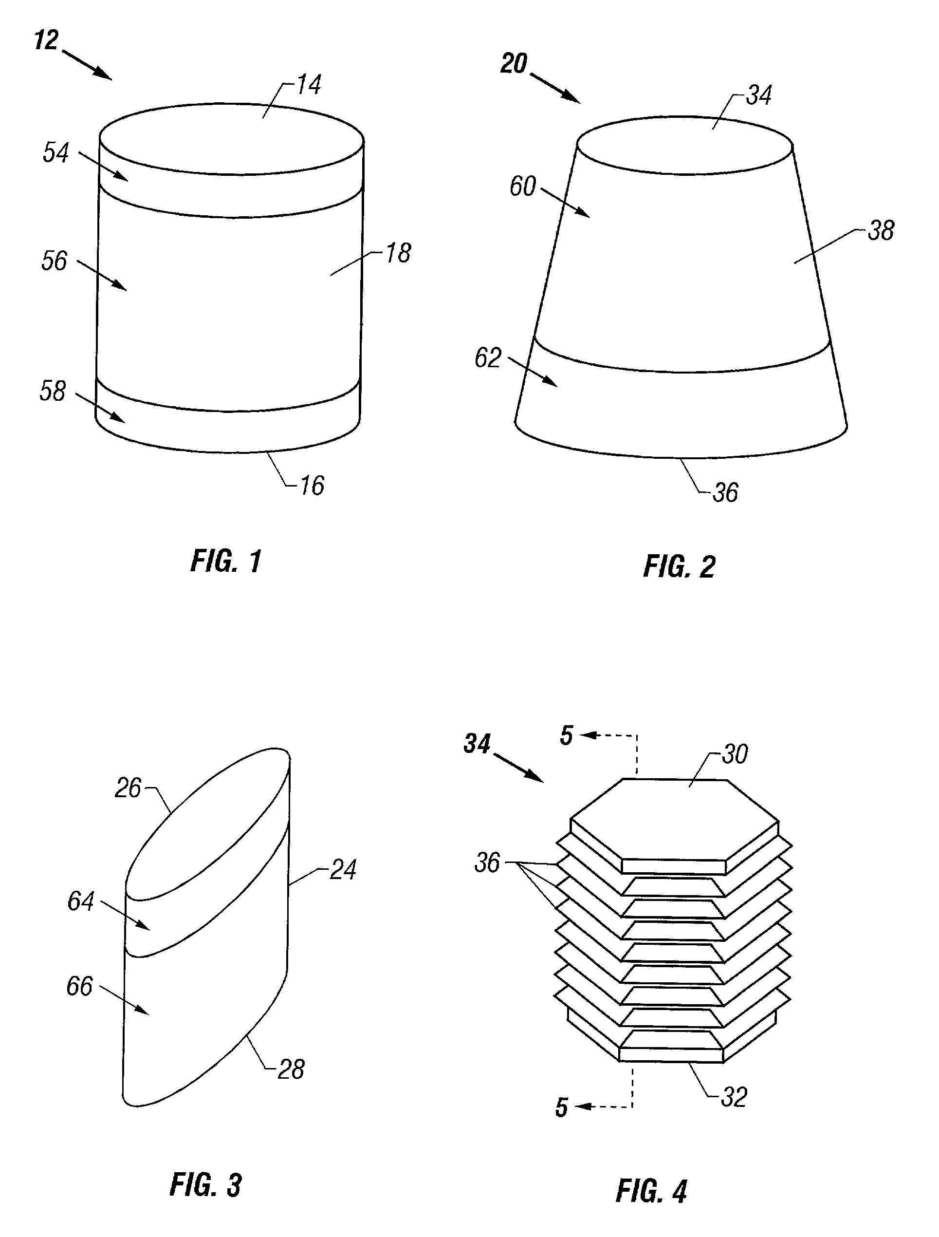
[0156] The cartilage plugs of the present invention may alternatively be used to anchor a flowable polymer to the subchondral bone. An implantation hole for the plug is drilled into the prepared bony base of the articular cartilage defect. Preparation of the bony base of the defect in this context entails the removal of loose tissue debris and exposure and / or surface modification of part or ll of the subchondral bone in the defect area by the surgeon. Using an inserter instrument that holds and drives the plug for implantantion, the base unit is inserted into the bone to a depth of approximately 50-60% of the plug height. The cylindrical devices are seated such that approximately half of the barbs or ridges on the outer surface of the plug engage the bony walls of the tunnel and the remaining half of the plug's external ridges remain exposed. The inserter tool is removed and rearmed with another anchor plug as necessary and the process is repeated. Multiple anchor plugs may be place...

embodiment 212

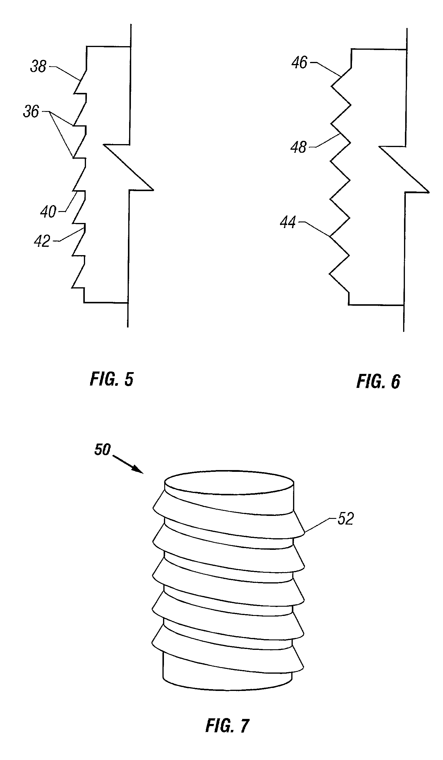
[0161] FIG. 12 is a bottom plan view of a bridged plug embodiment 212 of the present invention with two anchoring elements 214, 216 extending from a shared upper layer 218. FIG. 13 is a side view of a two-plug embodiment wherein the upper surface of the upper layer 220 has a curved shape while the lower surface 222 is flat. FIG. 14 is a side view of an embodiment wherein both the upper surface 224 as well as lower surface 226 of the upper layer 218a are both curved to cause the two anchoring elements 214, 216 to be angled toward one another. FIG. 15 shows yet another embodiment wherein both the top surface 228 and bottom surface 230 are flat and parallel to one another.

embodiment 232

[0162] FIG. 16 is a bottom plan view of another bridged plug embodiment 232 of the present invention wherein three anchoring elements 234, 236, 238 extend from a shared upper layer 240. FIG. 17 is a side view of a three-plug embodiment wherein the upper surface 242 of the upper layer 240 has a curved shape while the lower surface244 is flat. FIG. 18 is a side view of an embodiment wherein both the upper surface 246 as well as lower surface 248 of the upper layer 240a are both curved to cause the three anchoring elements 234, 236, 238 to be angled toward one another. FIG. 19 shows yet another embodiment wherein both the top surface 250 and bottom surface 252 are flat and parallel to one another.

[0163] FIGS. 20-22 are end views of bridged plug embodiments showing various cross-sectional shapes of the upper layer. The embodiment shown in FIG. 20 has a convex upper surface 254 while the upper surface 256 of embodiment shown in FIG. 21 is flat and the upper surface 258 of the embodiment ...


PUM

PropertyMeasurementUnit
diameteraaaaaaaaaa
depthaaaaaaaaaa
hardnessesaaaaaaaaaa

Abstract

A cartilage plug, which is made from a biocompatible, artificial material, that is used to fill a void in natural cartilage that has been resected due to traumatic injury or chronic disease. Alternatively, the plug may be relied upon to anchor a flowable polymer to subchondral bone. The plug is prefabricatable in any size, shape, and contour and may be utilized either singly or in a plurality to fill any size void for any application. The plug may be formed of a laminated structure to match the physiological requirements of the repair site. A plurality of anchoring elements may share a single upper layer.

Description

[0001] This patent application is a continuation-in-part of U.S. patent application Ser. No. 09 / 525,437, filed Mar. 14, 2000.[0002] This invention relates generally to the field of orthopedic surgery for the repair and replacement of damaged natural cartilage in a living mammal particularly human beings.[0003] More specifically, this invention relates to devices, methods, and instruments for the replacement of defective natural cartilage, where the defects are caused by traumatic injury which brings about sudden, acute damage to the cartilage, and / or by disease or the long term effects of unrepaired cartilage injuries, which over prolonged periods of time, cause achronic deterioration of the cartilage. Still more specifically, the invention relates to an artificial device, made from a biocompatible material, in the form of a cartilage replacement plug, which is used individually or in multiples, to fill void cavities in cartilage created by the resection and removal of damaged or di...

Claims


Application Information

Patent Timeline
Patent Type & Authority Applications(United States)
IPC IPC(8): A61B17/16A61L27/00A61B17/32A61B19/00A61F2/00A61F2/28A61F2/30A61F2/38A61F2/46A61L27/30
CPCA61B17/1604A61B17/1635A61B17/1637A61B17/1675A61B2019/306A61B2019/462A61F2/30756A61F2/30767A61F2/3094A61F2/3859A61F2/389A61F2/4618A61F2002/2839A61F2002/30004A61F2002/30011A61F2002/30016A61F2002/30067A61F2002/30112A61F2002/30113A61F2002/30125A61F2002/30138A61F2002/30143A61F2002/30146A61F2002/30151A61F2002/30153A61F2002/30154A61F2002/30169A61F2002/30205A61F2002/3021A61F2002/30224A61F2002/3023A61F2002/30273A61F2002/30276A61F2002/3028A61F2002/30289A61F2002/30329A61F2002/3038A61F2002/30448A61F2002/30454A61F2002/30457A61F2002/30502A61F2002/30583A61F2002/30616A61F2002/30759A61F2002/30772A61F2002/30795A61F2002/3085A61F2002/30879A61F2002/30892A61F2002/30894A61F2002/30904A61F2002/30957A61F2002/30971A61F2210/0085A61F2220/0025A61F2220/0033A61F2220/005A61F2220/0058A61F2230/0004A61F2230/0006A61F2230/0008A61F2230/0017A61F2230/0019A61F2230/0021A61F2230/0047A61F2230/0063A61F2230/0067A61F2230/0069A61F2230/0086A61F2230/0091A61F2240/001A61F2250/0014A61F2250/0019A61F2250/0023A61L2430/06A61F2002/4627A61B2090/036A61B2090/062A61F2002/30451A61F2002/305A61F2002/30331
Inventor SIMON, TIMOTHYABERMAN, HAROLD M.JACKSON, DOUGLAS W.
Owner ABS
Why Eureka
Try Eureka