
Method for post deposition of beta phase nickel aluminide coatings

a nickel aluminide coating and beta phase technology, applied in the direction of superimposed coating process, light beam reproducing, instruments, etc., can solve the problems of insufficient density, insufficient line-of-sight access, and insufficient density to achieve the full benefits of nial coating, so as to improve the efficiency, improve the density of a brittle coating, and improve the effect of corrosion and oxidation

Inactive Publication Date: 2005-03-10
GENERAL ELECTRIC CO
View PDF15 Cites 14 Cited by
  • Summary
  • Abstract
  • Description
  • Claims
  • Application Information

AI Technical Summary

Benefits of technology

[0013] An advantage of the present invention is the ability to tailor the surface roughness of a brittle, substantially stoichiometric β-phase aluminide coating such as NiAl or PtAl. In this way, the inherent advantages of a thermally sprayed β-phase composition can be utilized, while the brittle nature of the composition can be overcome so that the surface finish of the article can be modified to achieve the same results currently achievable for non-stoichiometric compositions that are either low in Ni or low in Al, or for stoichiometric compositions applied by PVD, VPA, or CVD methods. While the present invention was developed for use with β-phase NiAl, which is brittle, it may be used advantageously with any other coating with an unacceptably rough surface finish due to application techniques and that is inherently brittle or includes brittle phases, but which requires a smooth final surface finish for proper performance. Typically, these phases have a higher Al content than other, more ductile coatings and are identified as β-phases, and the coatings contain a substantial amount of the β-phases or are primarily β-phases.
[0014] Another advantage of the present invention is the ability to increase the density of a brittle coating without damaging it. While intended for use with β-phase NiAl, the present invention can be used with any aluminide or other coating that is brittle or contains brittle phases and has a brittle-ductile transition temperature. The methods of the present invention can modify the as-sprayed coating to achieve the required surface finish and desired density in order to take advantage of the improved corrosion and oxidation capabilities of the smoother, denser coating without damaging the brittle coating. Airfoils that have had their surface finish modified in accordance with the present invention will have a more aerodynamic gas flow path that serves to improve efficiency. Additionally, it is expected that furnace cycle testing (FCT) performance will improve as the surface finish is improved, which is an indication of improved thermal performance, or alternatively, resistance to spalling of a thermal barrier coating applied on top of the NiAl bond coat.
[0015] Still another advantage of the methods of the present invention is that they can be applied to both new airfoils and to airfoils that have undergone repair. These methods provide a simple, effective technique for achieving a smooth and dense β-phase NiAl coating that is cost effective and that can provide an adequate substitute for aluminide coatings that have a PtAl component.

Problems solved by technology

Currently, most as-manufactured NiAl applied as coatings by thermal spray techniques are neither sufficiently smooth nor sufficiently dense to achieve the full benefits of the NiAl coating.
This is particularly an issue in tight fitted regions and other regions where direct line-of-sight access is restricted which is required for thermal spray applications.
However, while the impingement techniques described in U.S. Pat. No. 6,403,165 produce a reasonably smooth NiAl coating, the density is not substantially increased.
Another limitation of known peening methods results from the structure of airfoils, which have small cooling holes in intricate patterns.
Using known room temperature peening methods, friable media must be avoided, since fractionation could result in the undesirable lodging of fractions in the cooling holes.

Method used


Image

  • Method for post deposition of beta phase nickel aluminide coatings
  • Method for post deposition of beta phase nickel aluminide coatings

Examples


Embodiment Construction

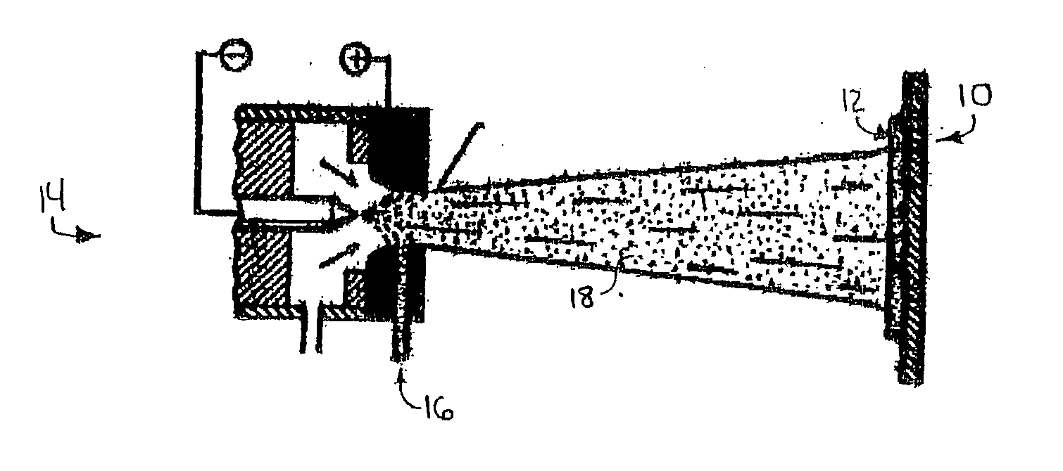
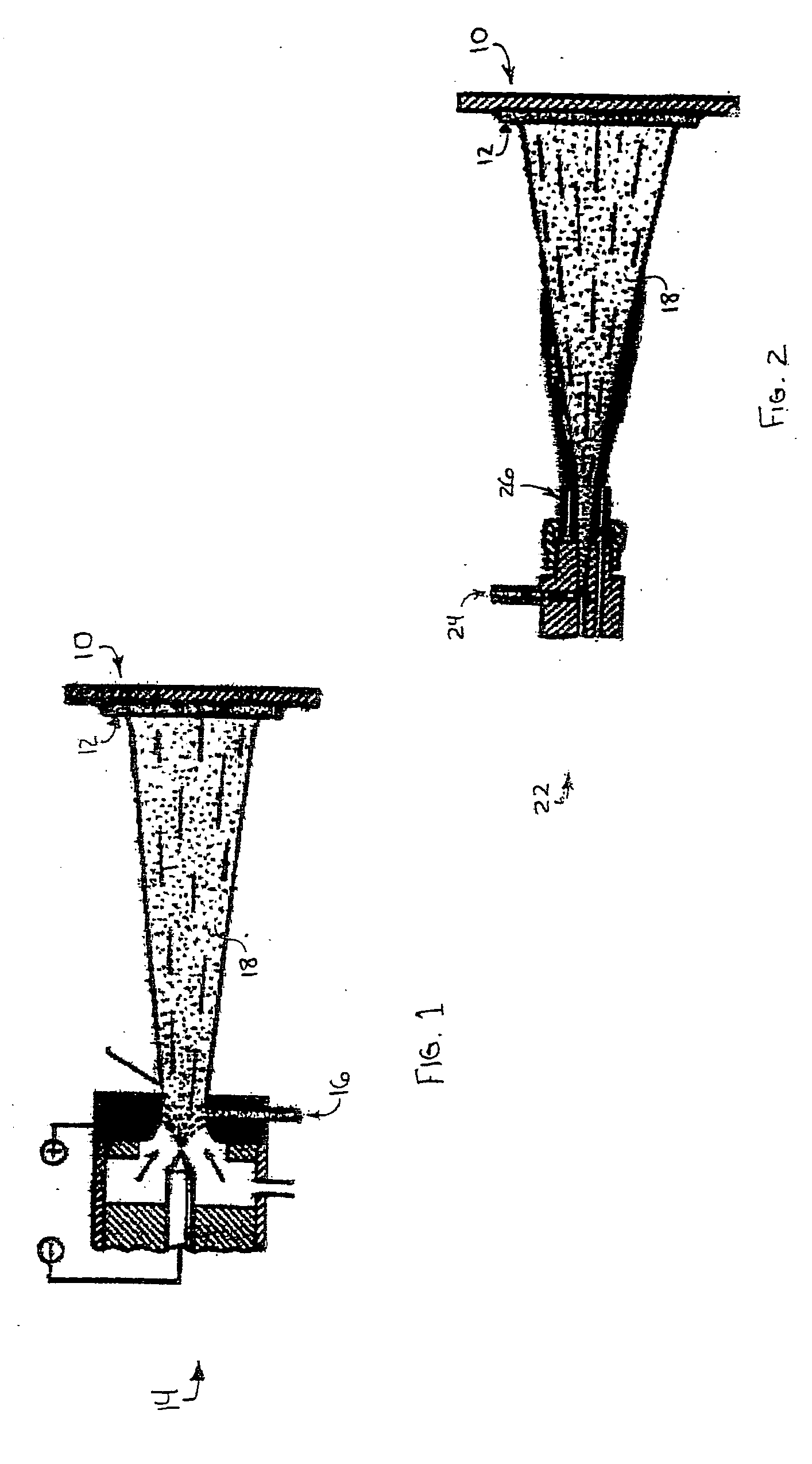
[0020] The present invention can be used on any turbine airfoil or flowpath part of a gas turbine engine coated with a brittle coating, such as a substantially stoichiometric β-phase NiAl coating, by a thermal spray process that results in a rough surface finish having a desired density and surface finish. The turbine airfoils typically requiring such protection are the high pressure turbine blades and high pressure vanes found immediately aft of the combustor portion of a turbine engine. While any β-phase NiAl or PtAl coating may be applied, it is preferred to use a substantially stoichiometric composition that includes small additions of rare earth elements such as zirconium (Zr), hafnium (Hf), yttrium (Y), lanthanum (La) and La-series elements, chromium (Cr), cesium (Cs), calcium (Ca), magnesium (Mg). Other elements may include cerium (Ce), praseodymium (Pr), neodymium (Nd), promethium (Pm), samarium (Sm), europium (Eu), gadolinium (Gd), terbium (Tb), dysprosium (Dy), holmium (Ho...


PUM

PropertyMeasurementUnit
diametrical sizeaaaaaaaaaa
temperatureaaaaaaaaaa

Abstract

A method for producing an article such as a turbine component that is coated with a β-phase, high aluminum content coating, such as substantially stoichiometric NiAl, and which has a surface finish suitable for application of a ceramic topcoat. The method involves heating the coated article to near the brittle-ductile transition temperature of the coating and impacting the coating with particles of a preselected size so that the brittle coating is not adversely affected by chipping or breakage. The impacting produces a surface finish of 120 micro-inches or finer so that a ceramic thermal barrier layer can be applied over the coating. The preferred method of improving the surface finish utilizes heated peening media to impact the heated coated article, thus allowing use of a broader selection of peening media.

Description

BACKGROUND OF THE INVENTION [0001] This invention is directed to a method for modifying a brittle environmental or bond coating applied to turbine engine components, and specifically to densification of substantially stoichiometric NiAl, and PtAl coatings having key quality characteristics required to protect the underlying turbine component in a high temperature, oxidative and corrosive atmosphere while also permitting application of long life thermal barrier topcoats. [0002] Many systems and improvements to thermal spray coating processes and systems have been set forth in the prior art for providing protection to turbine components, such as airfoils, turbine blades, turbine vanes, combuster components, turbine shrouds and other components which comprise the hot section of a gas turbine, from the combined effects of high temperatures, an oxidizing environment and hot corrosive gases and deposits. These improvements include new formulations for the materials used in components and ...

Claims


Application Information

Patent Timeline
Patent Type & Authority Applications(United States)
IPC IPC(8): C23C4/18C23C28/00
CPCC23C4/18Y02T50/67Y10T428/12993Y10T428/12736Y10T428/12944Y10T428/26Y02T50/60
Inventor RIGNEY, JOSEPH DAVIDMARTINA, MARK A.WEIMER, MICHAEL JAMES
Owner GENERAL ELECTRIC CO
Learn More