
Ozone generator system and ozone generating method

a generator system and ozone technology, applied in the direction of oxygen/ozone/oxide/hydroxide, physical/chemical process catalysts, corona discharge, etc., can solve the problems of increasing the by-product gas of no/sub>x, nitric acid clusters with bad influence, and ineffective argon gas, etc., to achieve the effect of suppressing the acceleration of corrosion of gas pipes, reducing the performance of condensing apparatuses, and increasing the efficiency of ozone generation

Active Publication Date: 2006-03-09
TOSHIBA MITSUBISHI-ELECTRIC IND SYST CORP
View PDF5 Cites 57 Cited by
  • Summary
  • Abstract
  • Description
  • Claims
  • Application Information

AI Technical Summary

Benefits of technology

[0070] According to the nitrogen-free ozone generator system and the nitrogen-free ozone generating method of the invention, the ozone generating efficiency can be adequately improved by the raw material gas not added with the nitrogen gas and mainly containing the oxygen gas, and a clean ozone gas (nitrogen-free ozone gas) containing no by-product material such as NOX or containing an unavoidable amount thereof can be obtained.
[0072] Besides, in the ozone generator system of the invention, since the gap interval of the discharge region is made 0.6 mm or less, the light intensity of the discharge light with a light wavelength in the range of 428 nm to 620 nm by the silent discharge is raised, the excitation of the photocatalytic material with a band gap of 2.0 eV to 2.9 eV is resultantly accelerated, and at the same time as the acceleration of dissociation of the oxygen gas, the ozone generation efficiency can also be raised.
[0073] Besides, since the nitrogen-free ozone generator system of the invention is used for the chemical vapor deposition apparatus or the ALD thin film deposition apparatus, in the chemical vapor deposition apparatus or the ALD thin film deposition apparatus, the clean ozone gas (nitrogen-free ozone gas) is effective in a cleaning step of removing moisture, hydrogen compound, and carbon compound, adsorbed on the substrate surface when a functionally effective thin film of a semiconductor or the like is produced, and further, it is effective in an ozone oxidation reaction step of transforming deposited metal into oxide metal by the ozone gas, and the quality of the oxide film of the thin film itself can be raised.
[0074] Besides, since the ozone generator system of the invention is used for the ozone condensing apparatus, the nitrogen-free ozone gas or the nitrogen suppression ozone gas can suppress the adsorption of an impurity gas in the ozone condensing apparatus, and the accumulation of the adsorption of the impurity gas is suppressed, so that reduction in performance of the condensing apparatus can be suppressed.
[0075] Besides, since the ozone generator system of this invention is used for the pulp bleaching apparatus, in the pulp bleaching apparatus, the nitrogen-free ozone gas or the nitrogen suppression ozone gas suppresses the generation of nitric acid due to the combination of moisture and NOX, and therefore, acceleration of corrosion of a gas pipe can be suppressed, and the lifetime of the apparatus can be prolonged.
[0076] Further, in the use of ozone in which the nitrogen gas may be contained in the oxygen gas, a trace amount of nitrogen (a suppressed amount of nitrogen) is added, so that the allowable band gap range of the photocatalyst provided on the dielectric or the electrode in the discharge region becomes 2.0 eV to 3.6 eV, and the ozone generation reaction is accelerated by using the discharge light (ultraviolet light) of the nitrogen. Thus, a trace amount of, specifically 10 ppm to 500 ppm, nitrogen gas is made to be contained in the oxygen gas, so that the ozone generation reaction can be accelerated. By the discharge light of the nitrogen, the photocatalytic material with a band gap of up to 3.6 eV can be used.

Problems solved by technology

Although patent document 1 discloses that a gas of helium, argon, or carbon dioxide is also effective as a gas other than the nitrogen gas addition, patent document 2 discloses that in the case of the high purity oxygen, the argon gas is not effective.
When the amount of the trace amount of nitric acid cluster contained is several hundred ppm or more, there are problems that rust of chromium oxide or the like is deposited by nitric acid on the inner surface of a stainless pipe as an ozone gas outlet pipe, a metal impurity is mixed into a clean ozone gas, the metal impurity in a reaction gas for a semiconductor manufacturing apparatus has a bad influence on the manufacture of a semiconductor, and the trace amount of the generated nitric acid cluster has a bad influence as a reaction poisonous substance on “an etching process of a silicon oxide film by ozone” or “ozone water washing of a wafer or the like” of the semiconductor manufacturing apparatus.
In the method of increasing the nitrogen additive rate, as described above, there is a problem that the by-product gas of NOX is increased.
Besides, when the gas flow rate is decreased, there are problems that the amount of ozone generation is extremely lowered, and production efficiency on the side of using the ozone becomes worse.
Thus, in the discharge space (discharge region), as the gas flow velocity becomes low, or the injected discharge power becomes high, the amount of generation of NOX as the nitrogen oxide is increased, and therefore, there are problems that the ozone generation efficiency is lowered, and the concentration of the extracted ozone is reduced.
i) Performance quality of the thin film is poor.
ii) Performance of the thin film is uneven.
As the cause of i) and ii), a metal impurity, a carbon impurity, a nitrogen impurity, hydrogen, or moisture is mixed at respective steps in the apparatus, and there are problems of the insulation of the thin film element, the increase of leak current, the fluctuation of performance, the deterioration of mechanical adhesion of the thin film itself, and the like.
In this ozone condensing apparatus, when an impurity such as nitrogen or nitrogen oxide (NOX) is contained in the ozone gas, not only the ozone gas, but also NOX contained in the gas is liquefied, and the adsorbed NOX is not desorbed in the desorption step but is accumulated on the silica gel, and there is a problem that the condensing ability of the condensing apparatus is lowered.
However, at the time of pulp bleaching, since an organochlorine compound such as harmful dioxin is discharged, there occurs a problem from the viewpoint of environment, and attention is given to an ozone bleaching apparatus which has bleaching ability and does not discharge a harmful material.
However, a large ozone apparatus is hard to realize, and there has been a fear that since nitrogen oxide is contained in the ozone gas, a pipe is broken due to corrosion of the pulp bleaching apparatus, and pulp fibers are damaged.
Besides, in the case where nitrogen gas is not added to the ozone generator system, a sufficient amount of ozone generation is not obtained, and there have been problems that the ozone generator system becomes large, electric power consumption becomes large, and an economical merit of the ozone bleaching apparatus is lost.

Method used


Image

  • Ozone generator system and ozone generating method
  • Ozone generator system and ozone generating method
  • Ozone generator system and ozone generating method

Examples


embodiment 1

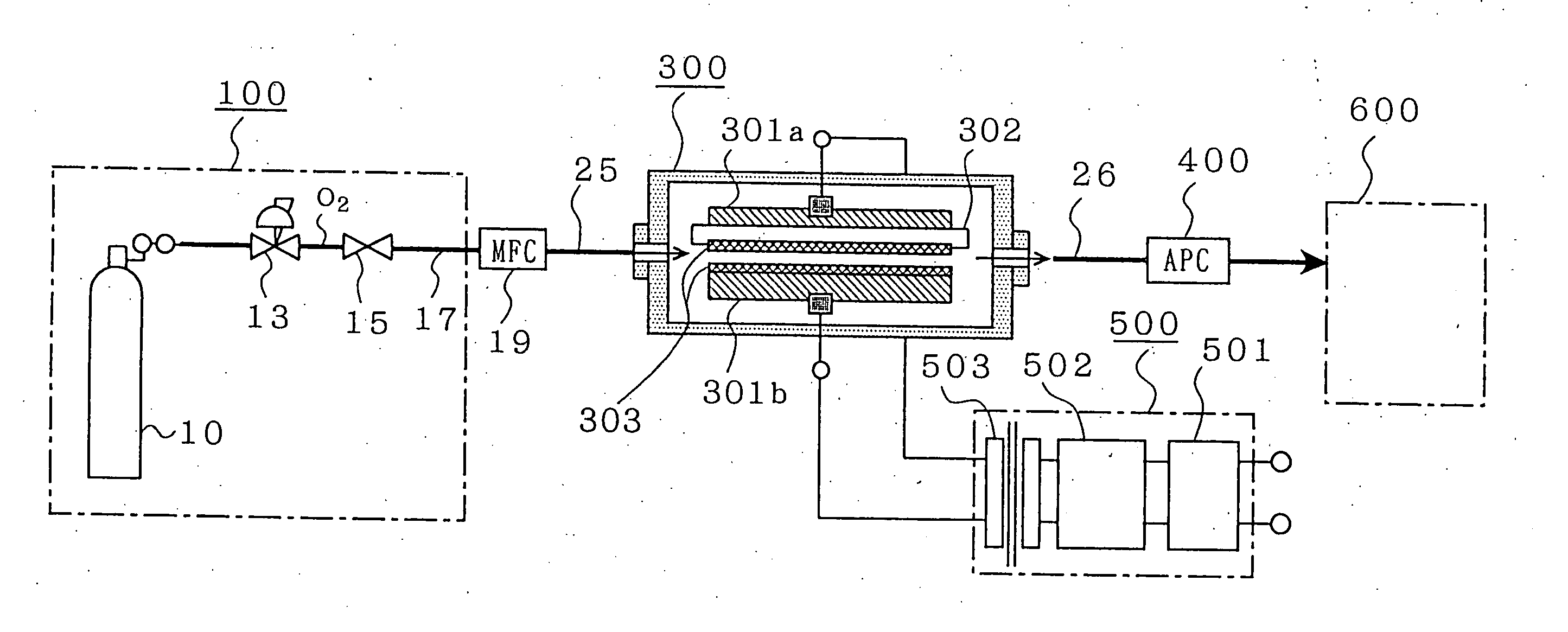
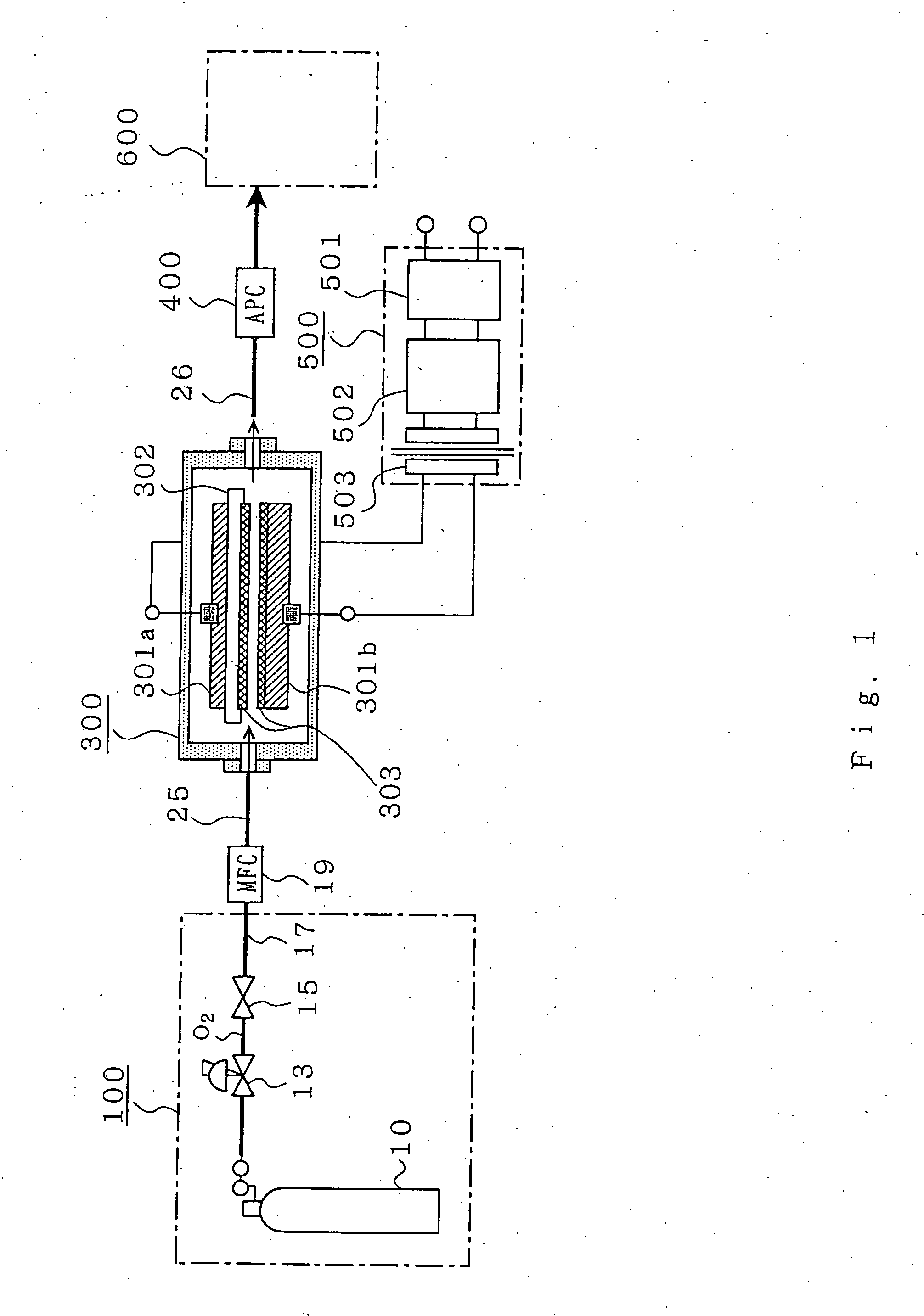
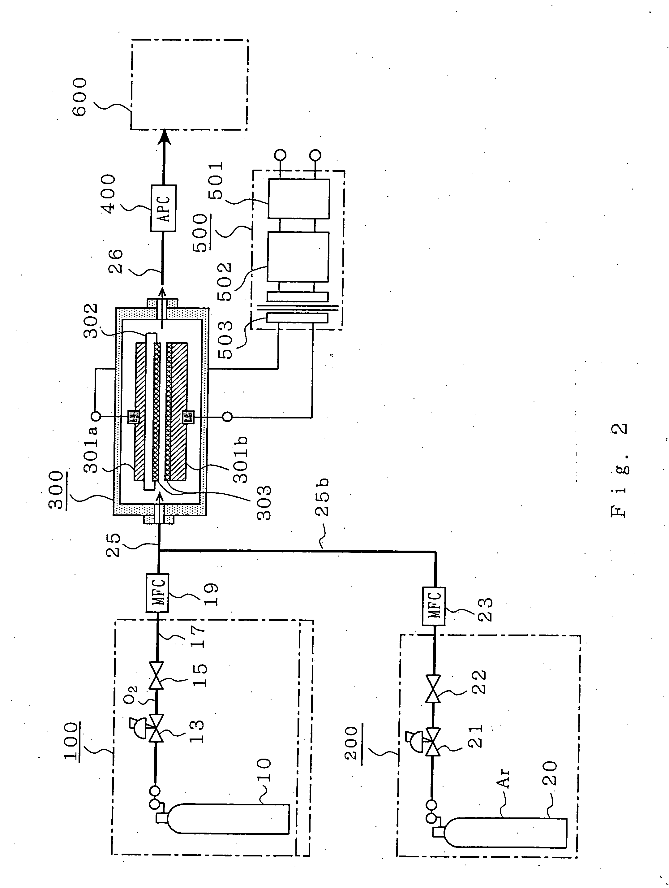
[0101] Embodiment 1 of the invention will be described with reference to FIG. 1 to FIG. 6. FIG. 1 is a block diagram showing a structure of a gas system in embodiment 1. FIG. 2 is a block diagram showing a structure in which in addition to the oxygen gas, an auxiliary gas such as a noble gas is added to the gas system of embodiment 1. FIG. 3 is a characteristic view showing an ozone concentration characteristic in embodiment 1. FIG. 4 is a schematic view showing a dissociation mechanism of an oxygen molecule into oxygen atoms by the oxygen molecule and a photocatalyst in embodiment 1. FIG. 5 is a schematic view showing a generation mechanism of ozone by triple collision of an oxygen atom and an oxygen molecule in embodiment 1. FIG. 6 is a schematic view showing a mechanism from an oxygen gas to ozone generation in the section of an ozone generator in embodiment 1. Incidentally, in the specification, the same characters in the respective drawings denote the same or like portions.

[01...

embodiment 2

[0157]FIG. 8 is a sectional schematic view for explaining an ozone generator used in embodiment 2. In embodiment 2, with respect to structure and method other than a specific structure and method explained here, the same structure and method as the structure and method in embodiment 1 described before are provided, and the same function is obtained.

[0158] In embodiment 1, the mechanism in which ozone can be generated mainly by the discharge of the oxygen gas has been described. However, in order to cause the apparatus to actually generate high concentration ozone efficiently, in addition to the simple application of the photocatalytic material, it is indispensable that the surface area of the photocatalytic material in the case where the applied photocatalytic material is applied to the discharge surface is made as large as possible. As one of means for increasing the surface area on which the discharge light impinges, a photocatalyst 303 applied to or sprayed on the surface of a d...

embodiment 3

[0165]FIG. 11 is a sectional schematic view for explaining an ozone generator used in embodiment 3. In embodiment 3, with respect to structure and method other than a specific structure and method explained here, the same structure and method as the structure and method in embodiment 1 described before are provided, and the same function is obtained. A roughness of about 1 μm to several μm, specifically, 1 μm to 50 μm is formed on a dielectric electrode surface, and photocatalyst powder (powder particle diameter is about 0.1 μm to 50 μm) is applied to or sprayed on the dielectric electrode surface on which the roughness is formed.

[0166] In this embodiment 3, the discharge surface of a dielectric 302 (or an electrode 301) is made rough, and the photocatalytic material described in embodiment 1 is applied to or sprayed on the dielectric electrode surface on which the roughness is formed. Thus, the contact surface area between the discharge light emitted in the discharge region and th...


PUM

PropertyMeasurementUnit
band gap energyaaaaaaaaaa
particle diameteraaaaaaaaaa
roughnessaaaaaaaaaa

Abstract

An ozone generating system and an ozone generating method producing ozone at a high concentration and operating at high efficiency, in which a raw material gas with no nitrogen added and mainly containing oxygen is used. The amount of generation of NOX by-product is null. A raw material gas not containing nitrogen and mainly containing oxygen is supplied to an ozone generator, an AC voltage is applied to produce discharge light having wavelength of 428 nm to 620 nm, a catalytic material containing a photocatalytic material with a band gap energy of 2.0 eV to 2.9 eV is provided on an electrode or a dielectric in a discharge region, gas pressure is kept at 0.1 MPa to 0.4 MPa, and ozone is generated.

Description

TECHNICAL FIELD [0001] The present invention relates to an ozone generator system and an ozone generating method, and particularly to an ozone generator system which includes a high voltage electrode and a low voltage electrode, causes discharge by the application of an AC voltage between them, and generates an ozone gas efficiently, and an ozone generating method. In particular, the invention relates to a nitrogen-free or nitrogen suppression ozone generator system and ozone generating method, in which a clean ozone gas is obtained. BACKGROUND ART [0002] In the prior art, following various techniques are developed. [0003] According to patent document 1, in an ozone generator system, a raw material gas, is supplied from a first raw material supply system for supplying a specified flow rate from an oxygen cylinder with a purity of 99.995% or higher, and from a second raw material supply system for supplying a specified flow rate of second raw material gas (nitrogen, helium, argon, or...

Claims


Application Information

Patent Timeline
Patent Type & Authority Applications(United States)
IPC IPC(8): H01J27/26B01J35/00B01J35/02C01B13/11H01T19/00H01T23/00
CPCB01J35/004C01B13/11C01B2201/12C01B2201/32C01B2201/34C01B2201/90C01B2201/64C01B2201/70C01B2201/80C01B2201/82C01B2201/60B01J35/39C01B13/10
Inventor TABATA, YOICHIROOKIHARA, YUJIROTETSUYASAITSU, MASAYUKIYOTSUMOTO, HATSUO
Owner TOSHIBA MITSUBISHI-ELECTRIC IND SYST CORP
Learn More