
Nano-composite structures, methods of making, and use thereof

a technology of nanocomposite and composite materials, applied in sustainable manufacturing/processing, non-aqueous electrolyte cells, non-metal conductors, etc., can solve the problems of poor cycle life characteristics of cells, increased cost of positive electrode materials, and higher cost of secondary batteries, so as to improve the electronic and ionic transport, the effect of efficient use of carbonous and high surface area

Active Publication Date: 2008-10-16
ROCHESTER INSTITUTE OF TECHNOLOGY
View PDF17 Cites 63 Cited by
  • Summary
  • Abstract
  • Description
  • Claims
  • Application Information

AI Technical Summary

Benefits of technology

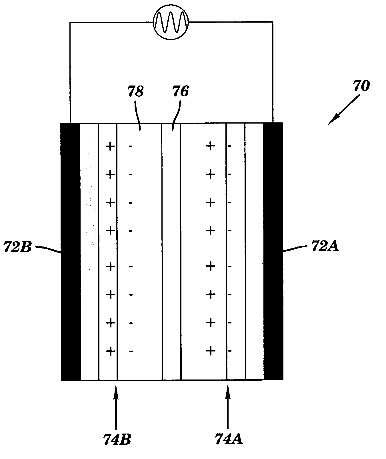
[0023]The nano-composite structures according to the present invention eliminate the necessity of metallic electrodes, such as copper, for the bulk support of active materials. The nano-composite structures improve the electronic and ionic transport within devices and allow the efficient use of carbonous and non-carbonous active materials. Furthermore, the nano-composite structures can be formed into electrodes that are lightweight and flexible, have a thermal stability exceeding 600° C., a high surface area, and high conductivity.
[0024]The nano-composite electrodes of the present invention reduce overall battery mass by replacing traditional metal foil supports (density ˜10 g / cm3) with a carbon based electrode (density ˜1 g / cm3) and provide a more efficient use of the materials present. The electrodes according to the present invention also allow higher mass and volume specific capacity and improved charge / discharge rates. Electrodes formed from the nano-composite materials of the present invention also have the potential to be cycled over a larger temperature range than conventional electrodes.

Problems solved by technology

While cells incorporating this material yield higher energy, assessing all the energy leads to material instability that in turn results in poor cycle life characteristics of the cells.
However, lithium-cobalt composite oxide electrodes require an expensive cobalt compound for raw material, increasing the cost of the positive electrode material, and resulting in the higher cost of the secondary battery.
However, lithium-nickel composite oxide electrodes have the following disadvantages: (i) discharge capacity is less in comparison to charge capacity; (ii) the irreversible capacity, or so called “retention” defined by the difference between the charge capacity and discharge capacity is considerable; and (iii) battery performance is comparatively easily degraded when used in high or low temperature environments.
While this improves cycle characteristics, it also narrows the range within which intercalation-deintercalation of the lithium ions is obtained, and tends to reduce discharge capacity.
Therefore, the edges of the graphite layers are aligned in a direction perpendicular to the positive electrode and, therefore, lithium ions which are deintercalated from the positive electrode cannot easily intercalate to the graphite layers during charging.
In particular, when a battery is charged at a high rate, lithium ions are insufficiently intercalated to the graphite layers and discharge characteristics consequently deteriorate.
In addition, since a lithium secondary battery is generally charged under constant current and constant voltage (CC-CV) and it is discharged under constant current, lithium ions that are deeply intercalated to the crystalline graphite layers are not fully deintercalated when the battery is discharged at high rates, thereby deteriorating cycle life characteristics.
Cycle life characteristics of a conventional lithium secondary battery further deteriorate because the lithium ions that deintercalate are insufficient to intercalate to the graphite layers, and too many lithium ions remain in the graphite.
Thus, when the amount of lithium intercalated by the anode is made to be greater than the theoretical amount upon charging or when charging is performed under condition of high electric current density, there will be an unavoidable problem of lithium deposition in a dendritic state (that is, in the form of a dendrite) on the surface of the anode.
This will result in causing internal-shorts between the anode and the cathode upon repeating the charge-and-discharge cycle.
Therefore, it is difficult for the lithium ion battery with the carbonous (i.e., graphite) anode to achieve a high capacity.
However, the charge-and-discharge cycle life is extremely short, because the metallic lithium reacts with impurities such as moisture and organic solvents present in the electrolyte solution and form an insulating film.
These factors lead to generating a dendrite of lithium upon repeating the charge-and-discharge cycle, resulting in internal-shorts between the anode and cathode.
As a result, the charge-and-discharge cycle life of the rechargeable battery is extremely shortened.
However, because the lithium alloy is hard it is difficult to produce a spiral-wound cylindrical rechargeable battery.

Method used


Image

  • Nano-composite structures, methods of making, and use thereof
  • Nano-composite structures, methods of making, and use thereof
  • Nano-composite structures, methods of making, and use thereof

Examples


example 1

Experimental Verification

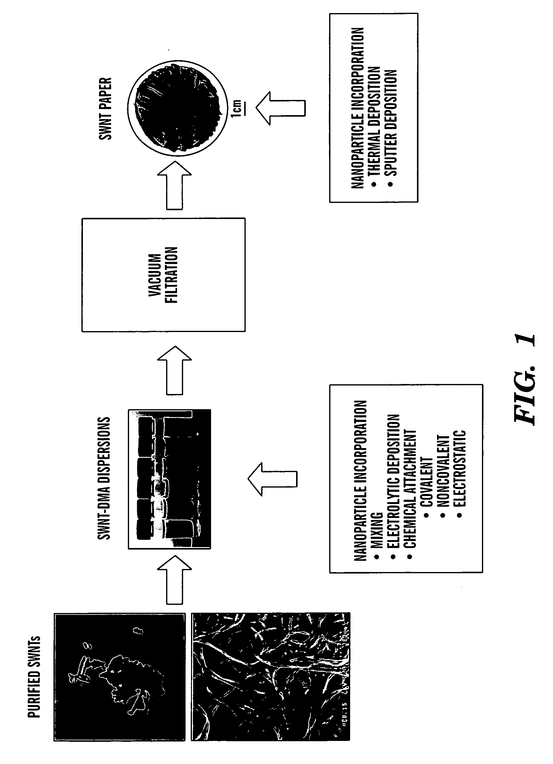
[0077]Single wall carbon nanotubes were synthesized using pulsed laser vaporization and purified using the NanoPower Research Labs' (at Rochester Institute of Technology, Rochester, N.Y.) thermal oxidation profiling procedure to achieve carbonous purities equivalent to the “100%” reference sample.

[0078]In the present case, the synthesis conditions were as follows: the Alexandrite laser pulse was rastered (corner to corner over 1 cm2 with 50% overlap of 100 μs pulses at a repetition rate of 10 Hz) over the surface of a graphite (1-2 μm) target doped with 2% w / w Ni (2. The reaction furnace temperature was maintained at 1150° C., with a chamber pressure of 700 torr under 100 sccm flowing Ar in a 46 mm inner diameter (50 mm outer diameter) quartz tube. Purification of the raw SWNT soot was purified by conventional acid reflux. The ratio of materials for refluxing was as follows: 250 mg raw soot added to the acid solution (150 mL H2O, 36 mL concentrated HNO3 (69-...

example 2

Electrochemical Cycling Results

[0080]The freestanding electrode paper nano Si-SWNT was electrochemically cycled to determine the lithium ion capacity. A 6 mm disc was punched out, weighing 1.181 mg and sandwiched opposite pure lithium metal with a Celgard-2325 spacer. The electrolyte solution used was 1 M LiPF6 in ethylene carbonate: propylene carbonate:dimethylcarbonate (1:1:2% vol / vol). The charge / discharge rate was at 74 mA / g and the corresponding charge / discharge data is shown in FIG. 6. The results show reversible capacities exceeding 900 mAhr / g.

example 3

Purified SWNT Papers as a Catalyst Support by Deposition of Germanium Particles

[0081]The freestanding electrode paper using purified SWNTs was used as a catalyst support for the deposition of germanium nanostructures (10 nm) using thermal evaporation. A 6 mm disc was punched out, weighing 1 mg and sandwiched opposite pure lithium metal with a Celgard-2325 spacer. The electrolyte solution used was 1 M LiPF6 in ethylene carbonate: propylene carbonate:dimethylcarbonate (1:1:2% vol / vol). The charge / discharge rate was at 124 mA / g and the corresponding charge / discharge data is shown in FIG. 7. The results show initial reversible capacities exceeding 400 mAhr / g. This is another demonstration of purified SWNT papers being used as a catalyst support by the deposition of germanium particles using thermal evaporation.


PUM


Abstract

The present invention relates to a nano-composite structure containing nanostructured carbon and nanoparticles. Also disclosed are methods of making the nano-composite structures. The present invention also relates to a lithium ion battery, a capacitor, a supercapacitor, a battery / capacitor, or a fuel cell containing the nano-composite structures of the present invention.

Description

[0001]This application claims the priority benefit of U.S. Provisional Patent Application Ser. No. 60 / 911,581, filed Apr. 13, 2007, which is hereby incorporated by reference in its entirety.[0002]The subject matter of this application was made with support from the United States Government under grant number NRO000-06-C-0241. The United States Government has certain rights.FIELD OF THE INVENTION[0003]The present invention relates to nano-composite structures; methods of their manufacture; and batteries, capacitors, and fuel cells containing the nano-composite structures.BACKGROUND OF THE INVENTION[0004]Lithium-based battery cells are an attractive energy source for portable applications due in part to their ability to provide relatively high energies and long cycle life. Lithium is the lightest of all the metals, with a high electrochemical potential, thus providing high energy densities. Rechargeable batteries using lithium as the electrochemical material are capable of providing h...

Claims


Application Information

Patent Timeline
IPC IPC(8): H01M6/02H01B1/06H01G9/022H01M8/02H01B1/24
CPCB82Y30/00Y02E60/50H01B1/122H01G9/058H01G11/36H01G11/42H01M4/38H01M4/587H01M4/621H01M4/625H01M4/9075H01M4/9083H01M4/92H01M4/921H01M4/923H01M4/925H01M4/926H01M10/0525Y02E60/122Y02E60/13H01B1/04H01G11/22H01M4/386H01M4/387Y02E60/10Y02P70/50
Inventor RAFFAELLE, RYNE P.LANDI, BRIAN J.CRESS, CORY D.
Owner ROCHESTER INSTITUTE OF TECHNOLOGY
Learn More