Electrochemical Double-Layer Capacitor Using Organosilicon Electrolytes

a technology of organosilicon and capacitor, which is applied in the direction of liquid electrolytic capacitor, electrochemical generator, etc., can solve the problems of inability to deliver high-power pulses, inability to stabilize at the operating voltage, and inability to store large amounts of energy in batteries or fuel cells, etc., to achieve high thermal and electrochemical stability, low equivalent series resistance, and high room temperature ionic conductivity

Active Publication Date: 2008-11-06
WISCONSIN ALUMNI RES FOUND
View PDF2 Cites 13 Cited by
  • Summary
  • Abstract
  • Description
  • Claims
  • Application Information

AI Technical Summary

Benefits of technology

[0025]Preferred electrolytes of the present invention have high room temperature ionic conductivity (hence providing lower equivalent series resistance), high thermal and electrochemical stability (therefore higher operating voltages and temperatures), and lower volatility, toxicity and flammability which in turn provides safety and performance enhancement. In addition, they are much less hydrophilic than certain other conventional electrolytes and therefore are more compatible with hydrophobic carbonaceous electrode materials and dielectric hydrophobic conventional polymer separators based on polyethylene (PE) or polypropylene (PP) or poly-tetrafluoroethylene (PTFE).
[0026]Particularly advantageous is that the present invention, in some embodiments, permits operation at high voltages see FIG. 9. Thus, our EDLCs, as compared to conventional supercapacitors, allow obtaining devices with high energy density: E=½ CV2, where E is energy stored in supercapacitor in Wh per kg, C is capacitance in Farads, V is electric potential in Volts; and power density: P=V2 / 4R, where P is a power density of the supercapacitor in W per kg, V is applied potential in Volts and R is equivalent series resistance in ohms. Also, our preferred electrolytes, and thus our preferred electrodes, are relatively easy to make, and can be synthesized in high yields from available and relatively inexpensive starting materials. They are also stable in storage and processing.
[0027]As some of our preferred electrolytes are solids with high room temperature ionic conductivity, the EDLC can be fabricated as an all-solid-state device. Such an all-solid-state supercapacitor can be safely packed in an ultra thin laminated foil material. The lamination operation is simple and inexpensive. Also, a rolled-sheet manufacturing process can be used to fabricate components of the solid organosilicon supercapacitor. This technology can be used in exceptionally cost effective, high speed and high volume industrial supercapacitor production.
[0028]The all-solid-state organosilicon supercapacitors do not need to be packed in rigid, hermetically sealed metal containers, which in turn would require complicated and cost consuming winding, canning and hermetic sealing operations. Hermetically sealed metal containers reduce effective volume, especially in large packs, resulting in increase of the weight and volume proportion of the housing metal material in liquid multicell devices, in comparison to the all-solid-state supercapacitors.

Problems solved by technology

In this regard, other energy storage devices such as batteries or fuel cells, which can store large amount of energy, cannot deliver high power pulses.
However, they were not stable at the operating voltages exceeding the electrolysis voltage of water (1.23 V) and that made organic liquid electrolytes preferable to aqueous electrolyte solutions for many commercial applications.
However, acetonitrile is a hazardous flammable and toxic material, which produces highly toxic products (HCN and CO) upon combustion and thermal decomposition.
They have lower ionic conductivity as compared to aqueous electrolytes or electrolytes based on acetonitrile, and this causes higher internal losses of stored energy and power density of the supercapacitor.
However, there was no teaching in these references to combine an organosilicon material with a high surface area material to create a supercapacitor electrode, or any suggestion to use ion-conducting organosilicon material as a binder or as a separator layer in supercapacitors.

Method used


Image

  • Electrochemical Double-Layer Capacitor Using Organosilicon Electrolytes
  • Electrochemical Double-Layer Capacitor Using Organosilicon Electrolytes
  • Electrochemical Double-Layer Capacitor Using Organosilicon Electrolytes

Examples


example 1

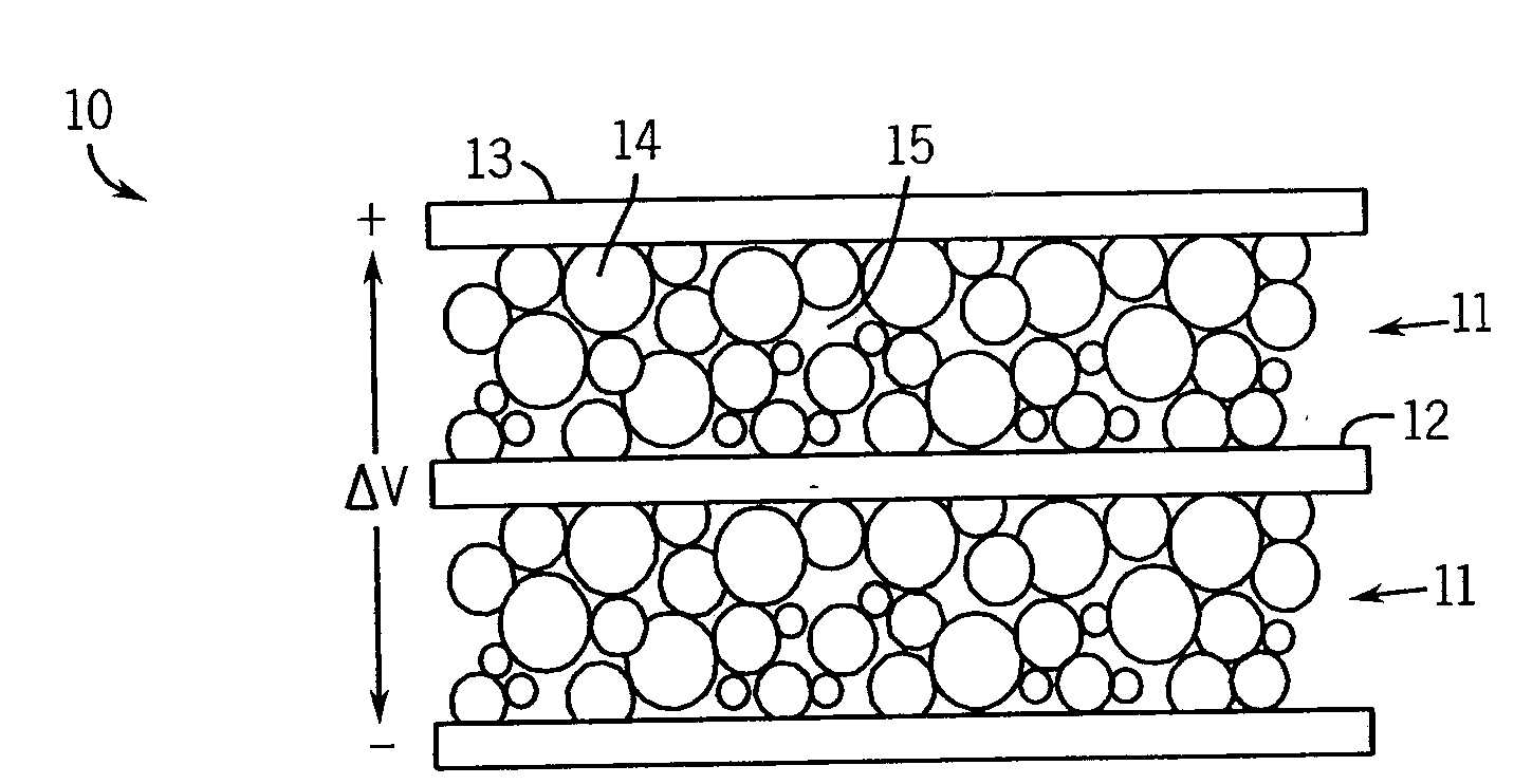
[0082]In this example an EDLC device was fabricated from activated carbon nanotubes deposited on stainless steel current collectors, using solid cross-linked organosiloxane polymer as the electrolyte, separator and as a binder.

[0083]Fabrication of the device began with preparation of the electrode / current collector assembly plates from activated carbon nanotubes powder. The multi-walled carbon nanotubes (MWCNTs) used for this study were produced by chemical vapor deposition and treated with hydrochloric acid at room temperature to extract catalyst and other impurities. The nanotubes powder then was washed with distilled water and dried.

[0084]Purified MWCNTs were refluxed with concentrated boiling nitric acid for about 10 hours for activation, and then washed with distilled water followed by rinsing with ethanol and drying in vacuum 10−3 mmHg at 60° C. Activated nanotubes then were dispersed by ultrasound sonication for 30 min in dimethylformamide (DMF) to prepare a colloidal suspens...

example 2

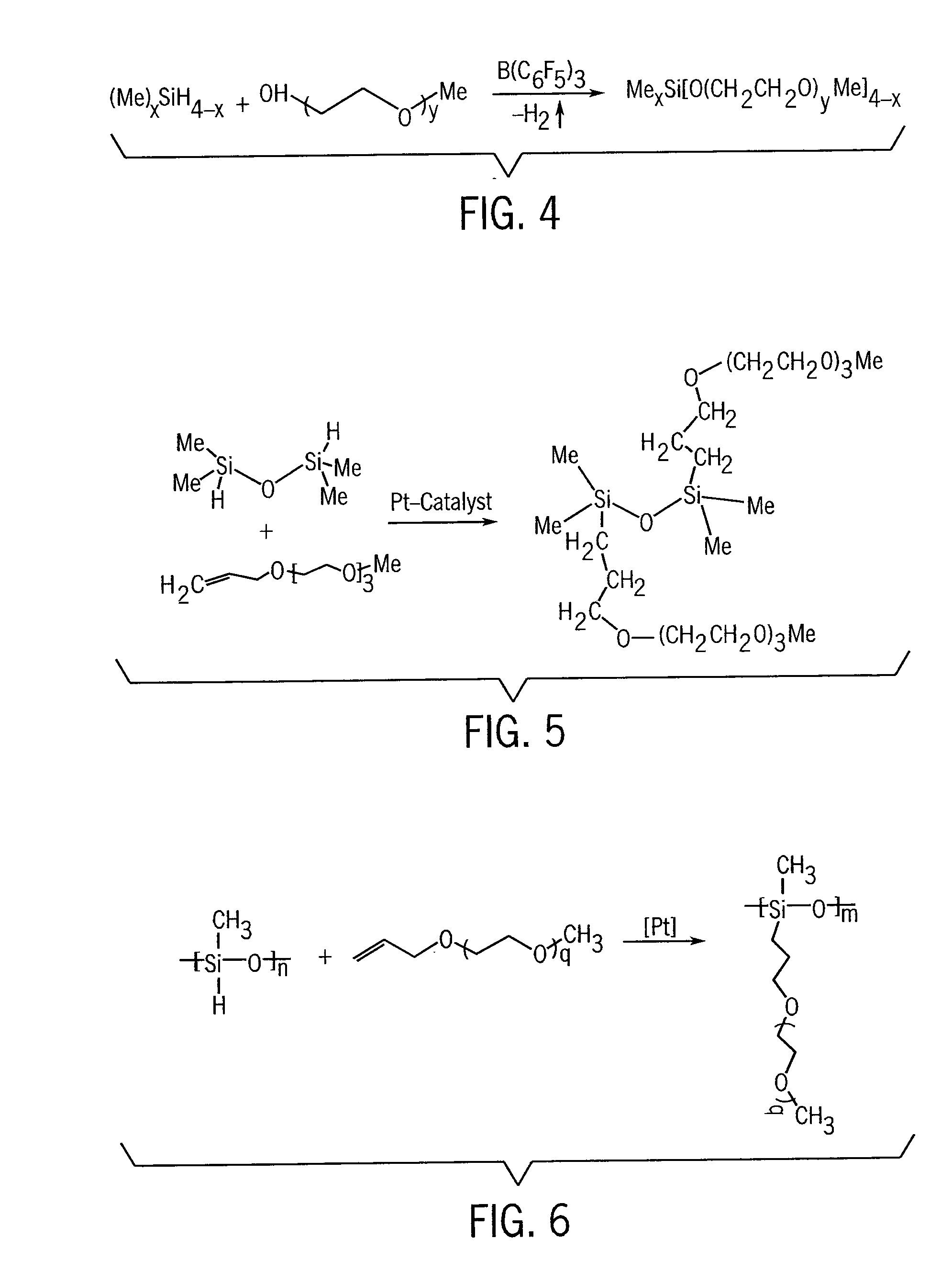
[0091]An electric double layer capacitor was prepared in the same manner as in Example 1, except that vertically aligned carbon nanofibers were used as a high surface area carbonaceous component of the electrode material (for two electrodes) instead of activated carbon nanotubes. We used a 0.8M solution of LiBOB in liquid disiloxane of FIG. 5 as the electrolyte, and used a PE / PP / PE tri-layer film (Celgard 3501, 25 μm) as a conventional separator.

[0092]Vertically aligned carbon nanofibers were grown on titanium / nickel coated stainless steel substrates using DC plasma-enhanced chemical vapor deposition. Typical growth conditions used flow rates of 80 standard cubic centimeters per minute (sccm) ammonia and 30 sccm acetylene, with a chamber pressure of 4 Torr and a DC power of 360 watts. Each metal layer in Ti / Ni coating had 50 nm thickness.

[0093]A two-electrode assembly, containing arrayed nanofiber electrodes of this example, was then placed into the Teflon Swagelok electrochemical c...

example 3

[0094]Attention is called to FIG. 10 where there is shown an alternative monolithic nanofiber based EDLC. There is shown a substrate 30 preferably made of silicon nitride. The substrate is then coated with a thin layer of molybdenum 31, which is in turn coated with a thin layer of titanium 32. Spaced strips of nickel 33 / 34 are then positioned along the structure.

[0095]Vertically aligned carbon nanofibers 35 were then grown on the nickel lines using DC plasma-enhanced chemical vapor deposition. The growth conditions we used were the same as in Example 2.

[0096]In this example, our most preferred form nanofibers were grown on silicon nitride substrates that we covered with a thin film consisting of 50 nm Mo, followed by 20 nm Ti, and finally 20 nm Ni as the top layer strips. SEM images (see FIG. 11) show that the nanofibers were vertically aligned with an average diameter of ˜75 nm. The length of the nanofibers was controlled by varying the duration of the growth. Nanofibers used for o...


PUM

PropertyMeasurementUnit
widthsaaaaaaaaaa
temperature ionic conductivityaaaaaaaaaa
thicknessaaaaaaaaaa

Abstract

Disclosed are supercapacitors having organosilicon electrolytes, high surface area / porous electrodes, and optionally organosilicon separators. Electrodes are formed from high surface area material (such as porous carbon nanotubes or carbon nanofibers), which has been impregnated with the electrolyte. These type devices appear particularly suitable for use in electric and hybrid electric vehicles.

Description

CROSS-REFERENCE TO RELATED APPLICATIONS[0001]This application is a divisional application of U.S. patent application Ser. No. 11 / 240,132, filed Sep. 30, 2005, now allowed.STATEMENT REGARDING FEDERALLY SPONSORED RESEARCH / DEVELOPMENT[0002]Not applicable.BACKGROUND OF THE INVENTION[0003]The present invention relates to electric double-layer capacitors (EDLCs), which are sometimes also referred to in the art as “electrochemical capacitors”, “supercapacitors”, or “ultracapacitors”. More particularly, it relates to the use of organosilicon electrolytes, and in some instances optionally an organosilicon separator and / or binder in such devices.[0004]A schematic example of a known type of EDLC is depicted in FIG. 1. This drawing shows an electrochemical double-layer capacitor 10 having two electrodes 11 which are kept from electrical contact by a separator 12. There are current collectors 13 at opposite ends of the device. The electrode consists of a porous material 14 and an electrolyte 15....

Claims


Application Information

Patent Timeline
Patent Type & Authority Applications(United States)
IPC IPC(8): H01G9/042
CPCH01G9/038H01G9/058H01G11/24H01G11/26H01G11/62Y02B10/30Y02E60/13Y02T10/7022H01G11/38H01G11/58Y02T10/70
Inventor DEMENTIEV, VIACHESLAV V.WEST, ROBERT C.HAMERS, ROBERT J.TSE, KIU-YUEN
Owner WISCONSIN ALUMNI RES FOUND
Why Eureka
Try Eureka