Process for Production of Aromatic Hydrocarbons

a technology of aromatic hydrocarbons and hydrocarbons, which is applied in the direction of hydrocarbon preparation catalysts, hydrocarbon oil treatment products, organic chemistry, etc., can solve the problems of reduced octane number of resulting products, difficult to produce high octane, and limited use of light hydrocarbons in petrochemical raw materials, so as to achieve higher yield

Active Publication Date: 2009-07-09
NIPPON OIL CORP +1
View PDF4 Cites 10 Cited by
  • Summary
  • Abstract
  • Description
  • Claims
  • Application Information

AI Technical Summary

Benefits of technology

[0052]This step is a step where the recycle gas containing methane and / or ethane produced through the hydrogen gas separation step and the low boiling point hydrocarbon gas separated in the aromatic hydrocarbon separation step are mixed with the feedstock aliphatic hydrocarbon. The mixing may be carried out in distribution pipes. The resulting mixture is introduced in the above-described conversion reaction step. The mix ratio of the recycle gas and low boiling point hydrocarbon gas per the feedstock aliphatic hydrocarbon is from 0.1 to 10 part by weight, preferably from 0.5 to 3 part by weight. The use of methane and / or ethane as the recycle gas gives the following advantageous effects. That is, since the aromatization reaction by dehydrogenation cyclization is an endothermal reaction, the catalyst layer temperature is decreased, resulting in a disadvantage for aromatization. Methane and / or ethane are hardly aromatized under these conditions and thus can be deemed an inert gas. When methane and / or ethane have heat, they function as a heat supplying medium and can suppress the temperature in the catalyst layer from decreasing and can proceed with the reaction favorably. As the result, the aromatic hydrocarbon yield can be increased. Further, the recycling can decrease the partial pressure of hydrogen generated in the conversion reaction of the feedstock and thus can proceed with the aromatization reaction favorably. As the result, the aromatic hydrocarbon yield can be increased. Moreover, since the gas velocity in the reaction layer is increased (GHSV is increased), the contact time of the reactants and the catalyst active sites are shortened, and thus an excessive reaction providing coke-like substances can be suppressed. As the result, a reduction in activity occurring as the lapse of the reaction can be inhibited thereby retaining the aromatic hydrocarbon yield at a higher level. In a commercial device, the recycle gas ratio should be determined in economical view.
[0053]FIG. 1 shows a flow chart illustrating exemplarily the operation of the process of the present invention.
[0054]A mixture 6 of a feedstock aliphatic hydrocarbon and a light hydrocarbon gas which is a recycle gas is charged in reaction layers of the number of n (n is an integer of 2 or greater), containing the catalyst composition and arranged in series in a conversion reaction step 1 to be converted to an aromatic hydrocarbon, and then separated into a liquid component (high pressure separated liquid 8) containing mainly an aromatic hydrocarbon and a light gas (high pressure separated gas 9) in a gas-liquid separation step 2. The high pressure separated liquid 8 is supplied to a step of separating the aromatic hydrocarbon to remove a low boiling point hydrocarbon gas 13 thereby recovering an aromatic hydrocarbon 14.
[0055]FIG. 2 shows one example of the conversion reaction step 1.
[0056]In the example shown in FIG. 2, the first stage reactor 16 and second stage reactor 17 are arranged in series, and a mixture 18 of a feedstock aliphatic hydrocarbon and a light hydrocarbon gas which is a recycle gas (corresponding to the mixture 6 in FIG. 1) is heated with a heating means 19 such as a heating furnace and introduced into the first stage reactor 16 to be converted. The first stage reactor 16 is provided with a catalyst in an amount of 30 percent by volume or less of the total catalyst amount and / or adjusted so that the aromatic yield in the effluent from the reactor 16 is from 0.5 to 30 percent by mass. The effluent 21 from the first stage reactor is heated again with a heating means 20 and then introduced into the second stage reactor 17 to be subjected to a conversion reaction again. The effluent 22 from the second stage reactor 17 may be heated again with a heating means such as a heating furnace and introduced into a third stage reactor, or alternatively may be introduced as the final effluent into the gas-liquid separation step 2 shown in FIG. 1. The reactor 16 and reactor 17 may be provided with another reactor 16′ and another reactor 17′, respectively so as to enable a continuous operation by carrying out the reaction and regeneration of the catalyst by removing coke depositing thereon by burning alternately in the reactors in the two lines.APPLICABILITY IN THE INDUSTRY
[0057]The process of the present invention can produce aromatic hydrocarbons from a light hydrocarbon containing mainly hydrocarbons having 2 to 7 carbon atoms at a higher yield, than the conventional processes.EXAMPLES

Problems solved by technology

However, it has been difficult to produce high octane number gasolines and aromatic hydrocarbons from a feedstock light hydrocarbon containing mainly hydrocarbons having 7 or fewer carbon atoms at a high yield with the conventional catalytic reforming processes because the conversion rate of the feedstock hydrocarbon to aromatics decreases with a decrease in the carbon atom number of the feedstock hydrocarbon, resulting in a decrease in the octane number of the resulting product.
Therefore, the usage of the light hydrocarbon is limited to petrochemical raw materials and raw materials for the production of city gas.
However, these catalytic reforming processes are large endothermal reactions and thus fail to proceed with the reaction because the reaction temperature decreases unless the reaction layers are efficiently supplied with heat, resulting in a problem that aromatic hydrocarbons can not be produced at a high yield.
However, this catalytic reforming of a gasoline fraction is different in the composition of the feedstock and catalyst system from the above-described processes for the production of aromatics from a light hydrocarbon.
Further, this patent document does not disclose the volume distribution of the plurality of reaction layers or the composition of the product outflowing from each of the reaction layers or suggest that the yield of the aromatics in the converted reaction product is significantly increased depending on the selection of the distribution or composition.
However, this process is complicated because different types of catalysts are used in those reforming zones.

Method used


Image

  • Process for Production of Aromatic Hydrocarbons
  • Process for Production of Aromatic Hydrocarbons

Examples


reference example 1

Production of crystalline aluminogallosilicate

[0059]Solutions (A) and (B) were prepared. Solution (A) contains 1,706.1 g of sodium silicate [J sodium silicate No. 3, SiO2: 28 to 30 percent by mass, Na: 9 to 10 percent by mass, balance: water, manufactured by Nippon Chemical Industrial Co., Ltd.] and 2,227.5 g of water. Solution (B) contains 64.2 g of Al2(SO4)3.14-18H2O [Reagent special grade, manufactured by Wako Pure Chemical Industries, Ltd.], 32.8 g of Ga(NO3)3.nH2O [Ga: 18.51 percent, manufactured by Soekawa Chemical Co., Ltd.], 369.2 g of tetrapropylammonium bromide, 152.1 g of H2SO4 (97 percent by mass), 26.6 g of NaCl and 2,975 g of water. Thereafter, solution (B) was gradually added to solution (A) at room temperature while stirring. The resulting mixture was vigorously stirred in a mixer for 15 minutes to crush the gel thereby producing a homogeneous fine emulsion. Thereafter, the mixture was put in a stainless steel autoclave and crystallized under conditions where the tem...

reference example 2

Preparation of Catalyst

[0061]Alumina powder (Cataloid AP, manufactured by JGC Catalysts and Chemicals Ltd.) was added to the crystalline aluminogallosilicate produced in Reference Example 1 so that the weight ratio of the aluminogallosilicate:alumina powder is 65:35, followed by addition of water. After the mixture was kneaded sufficiently, it was extruded and then dried at a temperature of 120° C. for 3 hours and calcined at a temperature of 600° C. under an air atmosphere for 3 hours. An about 2 normal ammonium nitrate aqueous solution was added to the extruded product at a rate of 5 ml per gram of the extruded product, followed by ion-exchange at a temperature of 100° C. for 2 hours. After this procedure was repeated 4 times, the product was dried at a temperature of 120° C. for 3 hours thereby producing an ammonium-type crystalline aluminogallosilicate shaped product. The product was made to have a size of 16 to 28 mesh and then calcined at a temperature of 600° C. under an air ...

example 1

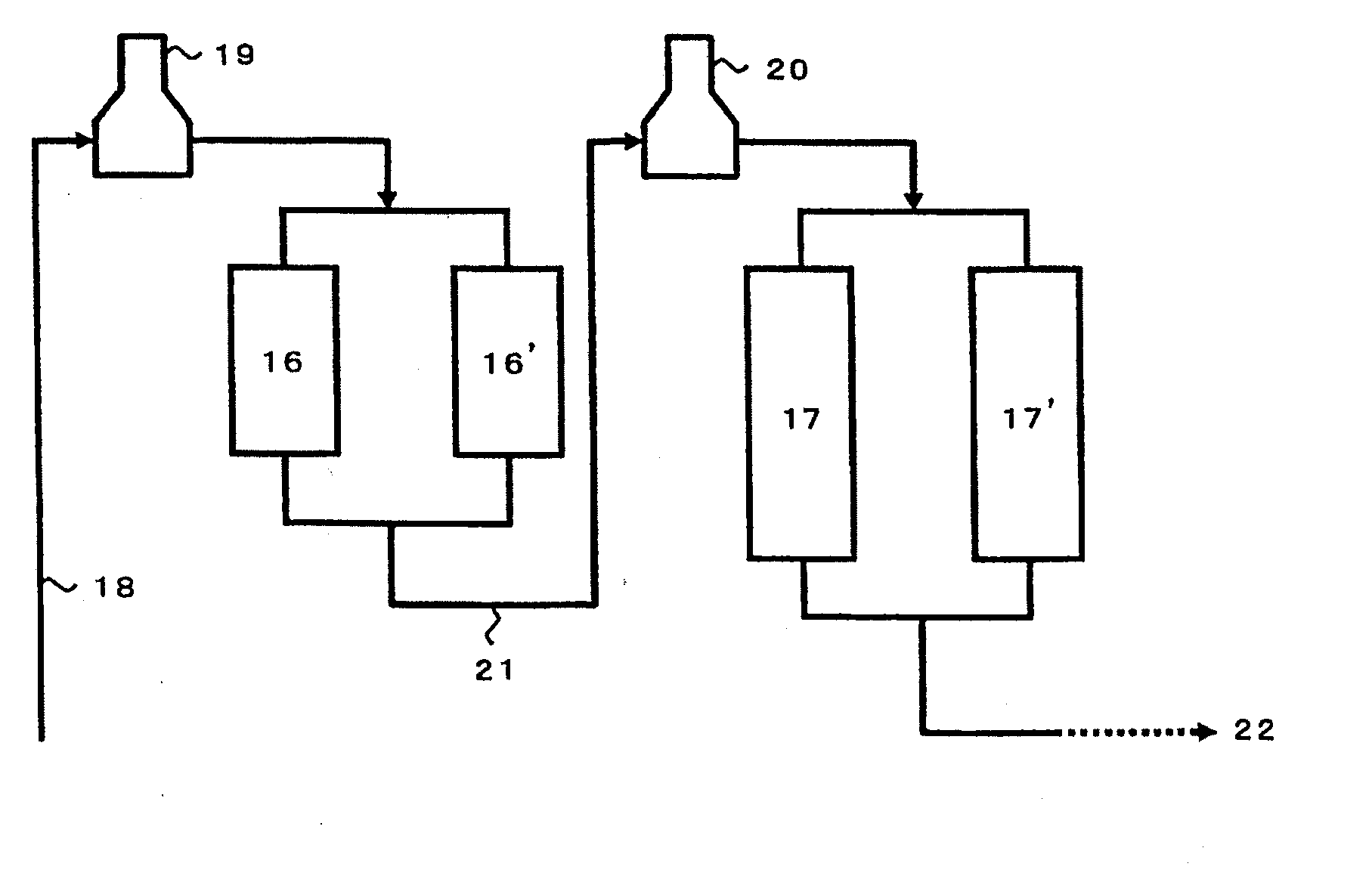
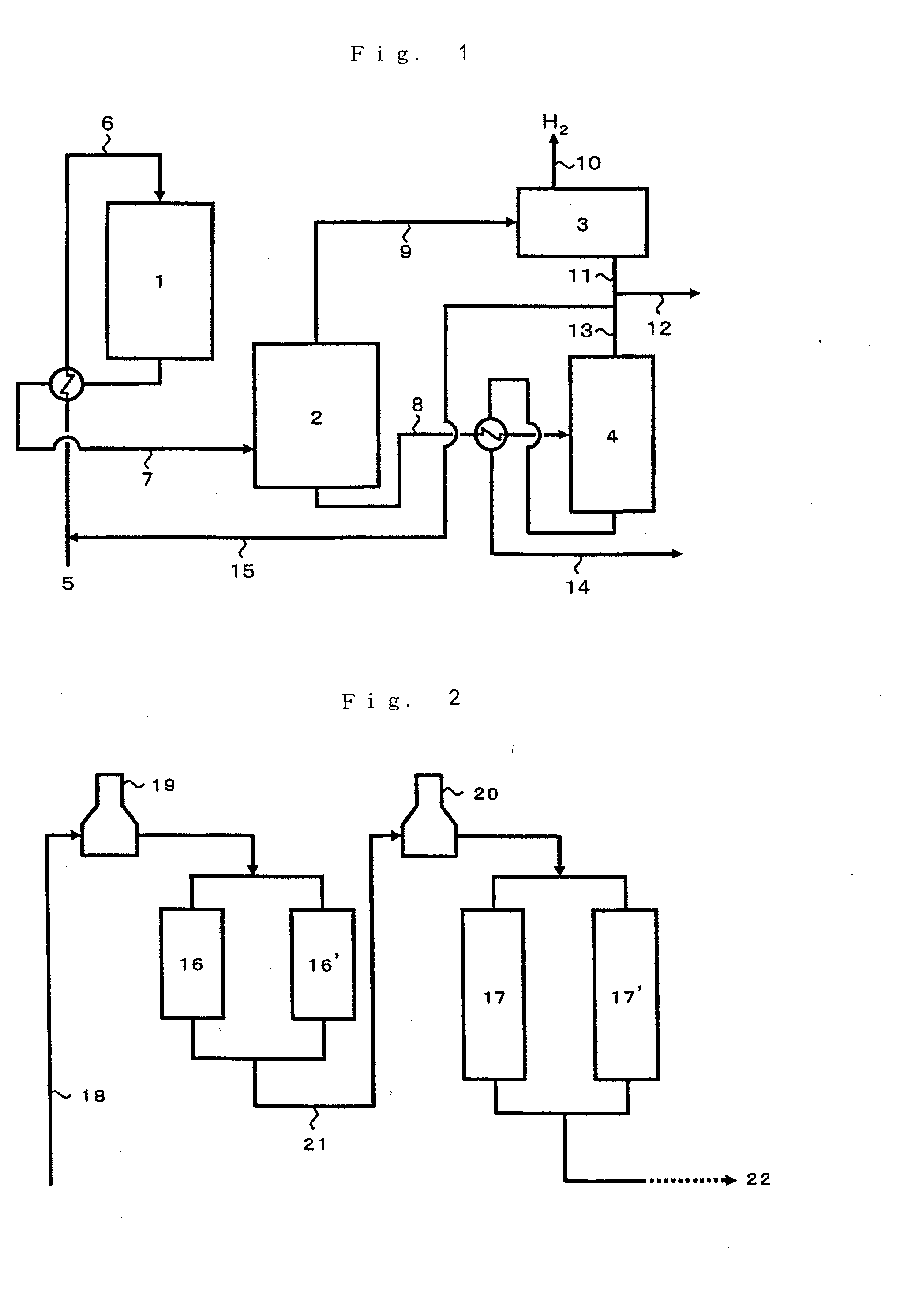
[0064]The hydrogen-type crystalline aluminogallosilicate catalyst of Reference Example 2 was used in an amount of 3 ml and packed in an amount of 50 percent by volume (1.5 ml) thereof into each of a first reactor and a second reactor. Using a reaction unit where these reactors are arranged in series, a conversion reaction was carried out at a temperature at the entrance of the first stage reactor of 550° C., a temperature at the entrance of the second stage reactor of 600° C., a pressure at the exit of the final stage reactor of 294 kPa (3.0 kgf / cm2) and an LHSV of 0.8 hr−1 by introducing nitrogen in an amount of 0.7 time by weight of the feedstock naphtha, as a gas simulating a recycle gas. The reaction results are set forth in Table 1 below. The reaction was carried out for 24 hours, and the effluent was analyzed in the same manner as Comparative Example 2. The results are set forth in Table 1.


PUM

PropertyMeasurementUnit
diameteraaaaaaaaaa
boiling pointaaaaaaaaaa

Abstract

The present invention provides a process for producing aromatic hydrocarbons at a sufficiently high yield, from a light hydrocarbon containing mainly hydrocarbons having 7 or fewer carbon atoms. The process of the present invention comprises bringing a feedstock containing mainly light hydrocarbons having 2 to 7 carbon atoms into contact with a catalyst composition comprising at least a gallium-containing crystalline aluminosilicate wherein a reaction step for converting the feedstock to aromatic hydrocarbons comprises at least two or more reaction layers formed of the catalyst composition, arranged in series and heating means arranged either between or in the reaction layers, the amount of the catalyst in the first stage reaction layer is 30 percent by volume or less of the total catalyst volume, and / or the yield of the aromatics in the product outflowing from the first reaction layer is from 0.5 to 30 percent by mass.

Description

FIELD OF THE INVENTION[0001]The present invention relates to a process for producing aromatic hydrocarbons from a light hydrocarbon containing mainly hydrocarbons having 2 to 7 carbon atoms, used as the feedstock.BACKGROUND OF THE INVENTION[0002]Conventionally, catalytic reforming of straight run naphtha with a platinum / alumina catalyst has been employed widely for commercial purposes in order to produce gasoline with a higher octane number or aromatic hydrocarbons. The feedstock naphtha for the catalytic reforming is a fraction with a boiling point of 70 to 180° C. when an automobile gasoline is intended to be produced and a fraction with a boiling point of 60 to 150° C. when aromatic hydrocarbons such as xylene, that is BTX, are intended to be produced. However, it has been difficult to produce high octane number gasolines and aromatic hydrocarbons from a feedstock light hydrocarbon containing mainly hydrocarbons having 7 or fewer carbon atoms at a high yield with the conventional...

Claims


Application Information

Patent Timeline
Patent Type & Authority Applications(United States)
IPC IPC(8): C07C15/00
CPCC07C2/84C07C2529/87C10G35/095C10G45/68C10G2400/30C10G50/00C10G2300/4025C07C15/00
Inventor SUZUKI, YUSHIASANO, TSUYOSHI
Owner NIPPON OIL CORP
Why Eureka
Try Eureka