

Process for Producing Highly conducting and Transparent Films From Graphene Oxide-Metal Nanowire Hybrid Materials
- Summary
- Abstract
- Description
- Claims
- Application Information
AI Technical Summary
Benefits of technology
Problems solved by technology
Method used
Image

Examples
example 1
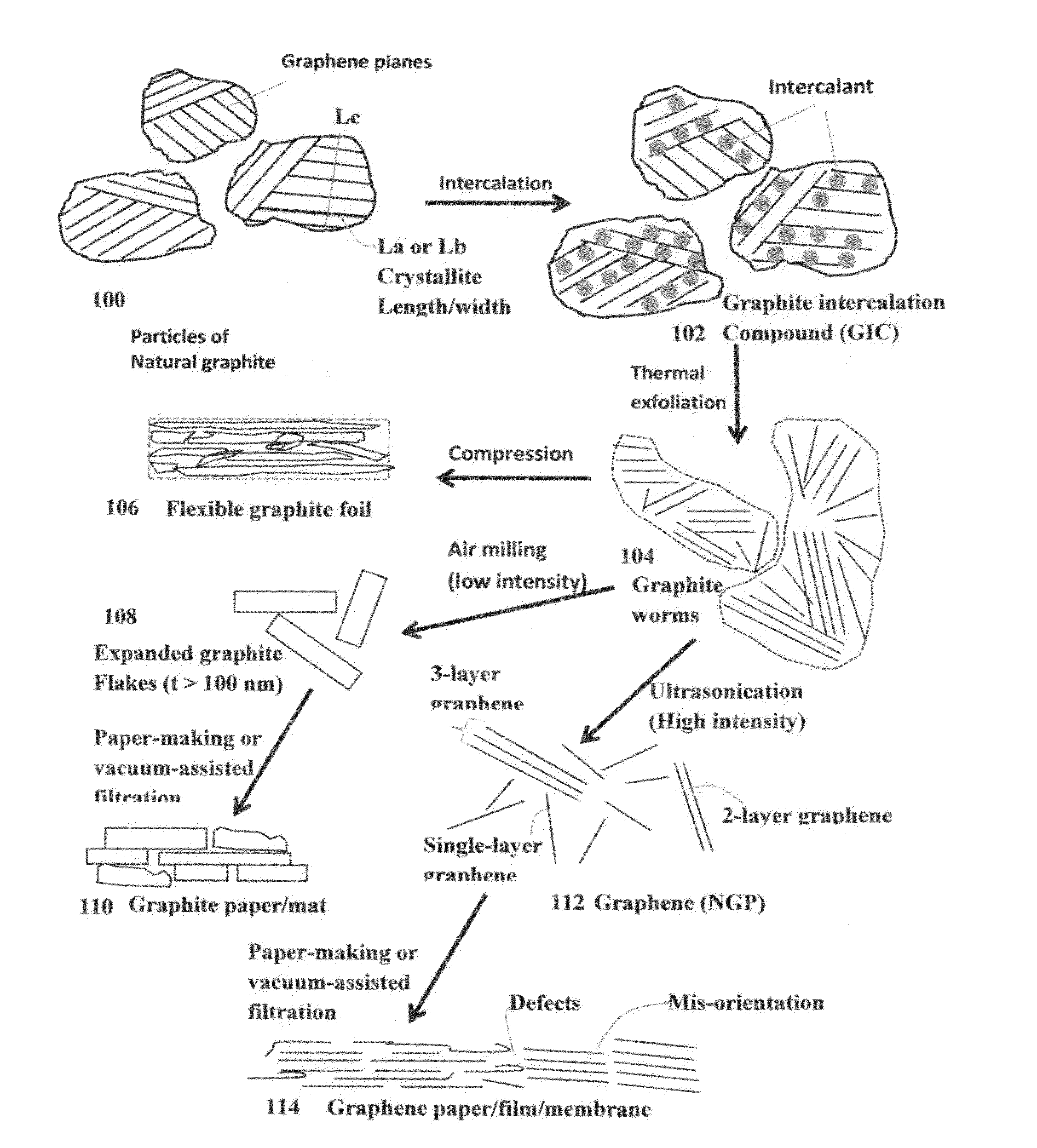
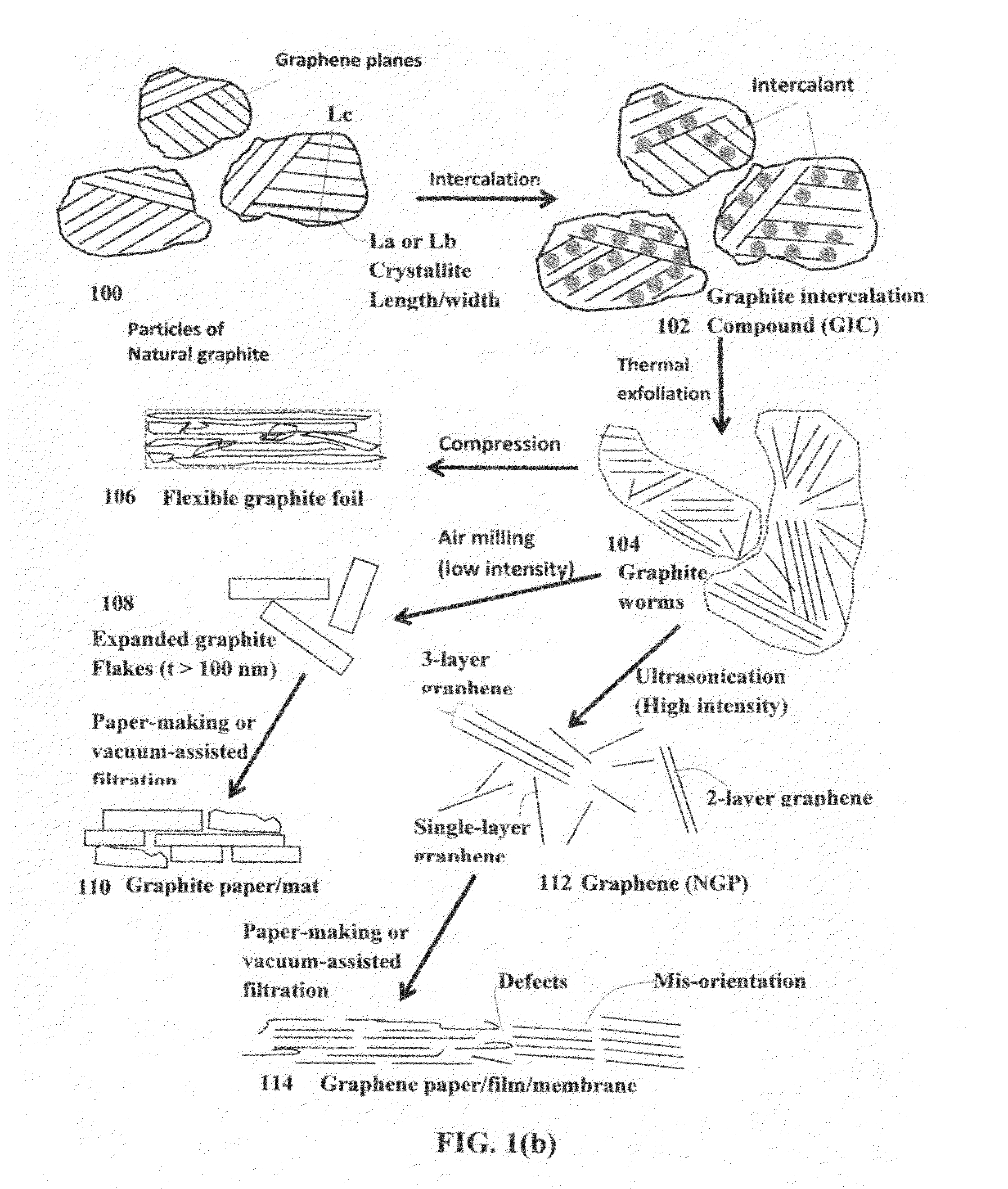
Thermal Exfoliation and Separation of Graphite Oxide
[0091]Graphite oxide was prepared by oxidation of graphite flakes with sulfuric acid, nitrate, and permanganate according to the method of Hummers [U.S. Pat. No. 2,798,878, Jul. 9, 1957]. Upon completion of the reaction, the mixture was poured into deionized water and filtered. The graphite oxide was repeatedly washed in a 5% solution of HCl to remove most of the sulphate ions. The GO sample was then washed repeatedly with deionized water until the pH of the filtrate was neutral. After this procedure, we followed two routes to prepare RGO and RGO- metal nanowire suspensions:
[0092]In the first route, portion of the GO-deionized water suspension (not a GO gel) was cast onto a glass surface to form a GO film, which was then thermally reduced at 150° C. for 2 hours in vacuum and then 500° C. in a flowing nitrogen / hydrogen condition in a tube furnace to obtain a RGO film. Metal nanowires were poured into the remaining portion of the GO ...
example 2
Preparation of Graphene Oxide (GO) Gel
[0094]Graphite oxide gel was prepared by oxidation of graphite flakes with an oxidizer liquid consisting of sulfuric acid, sodium nitrate, and potassium permanganate at a ratio of 4:1:0.05 at 30° C. When natural graphite flakes (particle sizes of <14 μm) were immersed and dispersed in the oxidizer mixture liquid, the suspension or slurry initially appeared optically opaque and dark. The suspension remained opaque during the first 52 hours of reaction. However, the suspension gradually turned optically translucent (a little cloudy) when the reaction time exceeded 52 hours, and the color of the suspension changed from black to dark brown. After 96 hours, the suspension suddenly became an optically transparent solution with light brown color. The solution appeared very uniform in color and transparency, indicating the absence of any dispersed discrete objects. The whole solution behaves like a gel, very similar to a typical polymer gel.
[0095]Surpri...
example 3
Characterization of Thin Films of Silver Nanowires (AgNW), AgNW / RGO Hybrid (conventional), and AgNW / RGO (GO-derived) Hybrid Materials
[0096]Silver nanowires were purchased from Seashell Technologies (La Jolla, Calif., USA) as suspension in isopropyl alcohol with concentrations of 25 mg / ml. A small volume of dispersion was diluted down to approximately 1 mg / ml with isopropyl alcohol. This was subjected to half-an-hour sonication in a sonic bath. Then, this suspension was applied to a 50 mm×100 mm poly(ethylene terephthalate) (PET) substrates by a manually controlled wire-wound, i.e., pushing the suspension on top of the substrate with a rod.
[0097]In addition, AgNW films were prepared by spin-coating AgNW inks on glass substrates. To prepare AgNW films on glass substrates, we treated glass substrates with UV / Ozone to make hydrophilic surfaces for AgNW. Then, AgNW ink was spin-coated on a glass substrate and dried at 120° C. for 5 min. Several AgNW films were prepared by changing spin-c...
PUM
| Property | Measurement | Unit |
|---|---|---|
| Fraction | aaaaa | aaaaa |
| Fraction | aaaaa | aaaaa |
| Fraction | aaaaa | aaaaa |
Abstract
Description
Claims
Application Information