

Thermoplastic carbon composite electrodes
- Summary
- Abstract
- Description
- Claims
- Application Information
AI Technical Summary
Benefits of technology
Problems solved by technology
Method used
Image

Examples
example 1
and Methods
Reagents
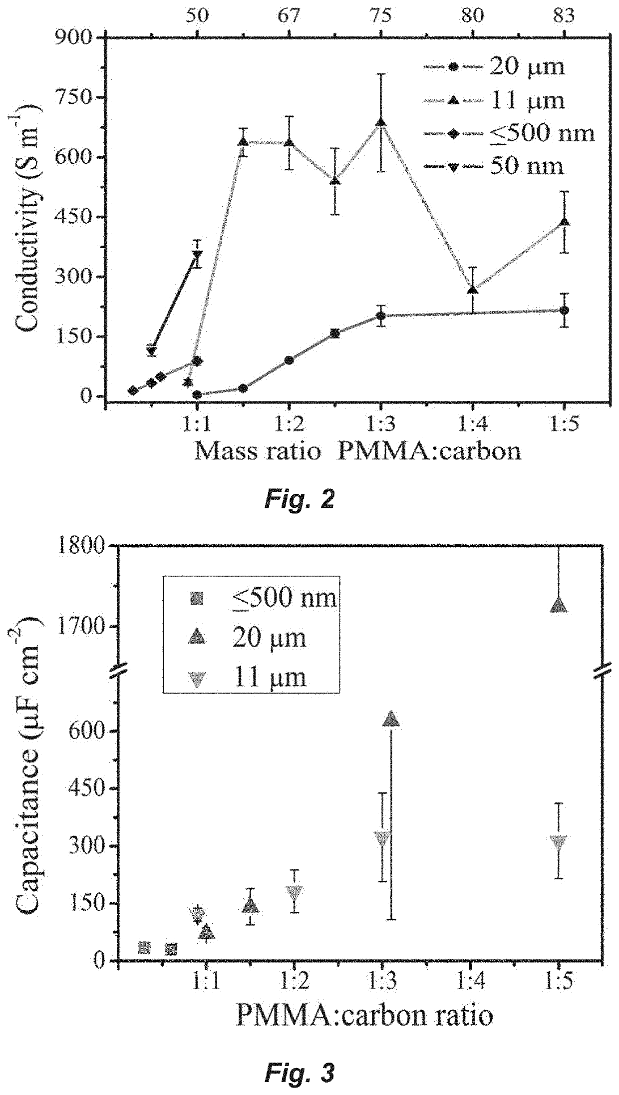
[0124]Poly(methyl methacrylate) (PMMA) was Optix from Plaskolite and was used as the TPE binder and the template material. Carbon sources were synthetic graphite powder (7-11 μm, 99%. Alfa Aesar), acetylene carbon black (100% compressed, STREM Chemicals), synthetic graphite powder (<20 μm, Sigma-Aldrich), and carbon nanopowder (≤500 nm, 99.95% trace metal basis, Sigma-Aldrich). Chemicals were potassium ferricyanide (99%, Sigma-Aldrich), potassium phosphate monobasic (99.8%, Sigma-Aldrich), potassium phosphate dibasic (98%, EMD Chemicals), potassium chloride (99-100.5%, Sigma-Aldrich), hexaammineruthenium(III) chloride (Sigma-Aldrich), ascorbic acid (99%, Sigma-Aldrich), dopamine hydrochloride (Sigma-Aldrich), iron(III) nitrate nonahydrate (Fisher), and 1,2-dichloroethane (Fisher).
Conductivity Measurements
[0125]Through-plane resistivity (inverse of conductivity) was measured by a two-point probe (Fluke 187 multimeter, accuracy of 0.01Ω) placed on opposing faces of ...
example 2
xperimental Procedures
[0129]Electrochemistry was performed with a CHI 660 potentiostat, using a calomel reference saturated with KCl. The counter electrode for three electrode experiments was a specially fabricated PMMA cell with a volume ˜1.3 mL, coated with PMMA / graphite, also a block of stainless-steel mesh was laid into the bottom of the cell to provide additional surface area. The counter electrode had nearly ˜500× the surface area as the working electrode. Potassium ferricyanide (Sigma) solutions were 10 mM [Fe(CN)6]−3 and 10 mM [Fe(CN)6]−4, using a 0.1M phosphate buffer solution at pH of 7.1. Ferricyanide impedance measurements were done at the E1 / 2 of the redox couple taken from cyclic voltammetry at 100 mV / s, perturbation voltage was 10 mV, with a frequency range from 100000 Hz to 0.1 Hz.
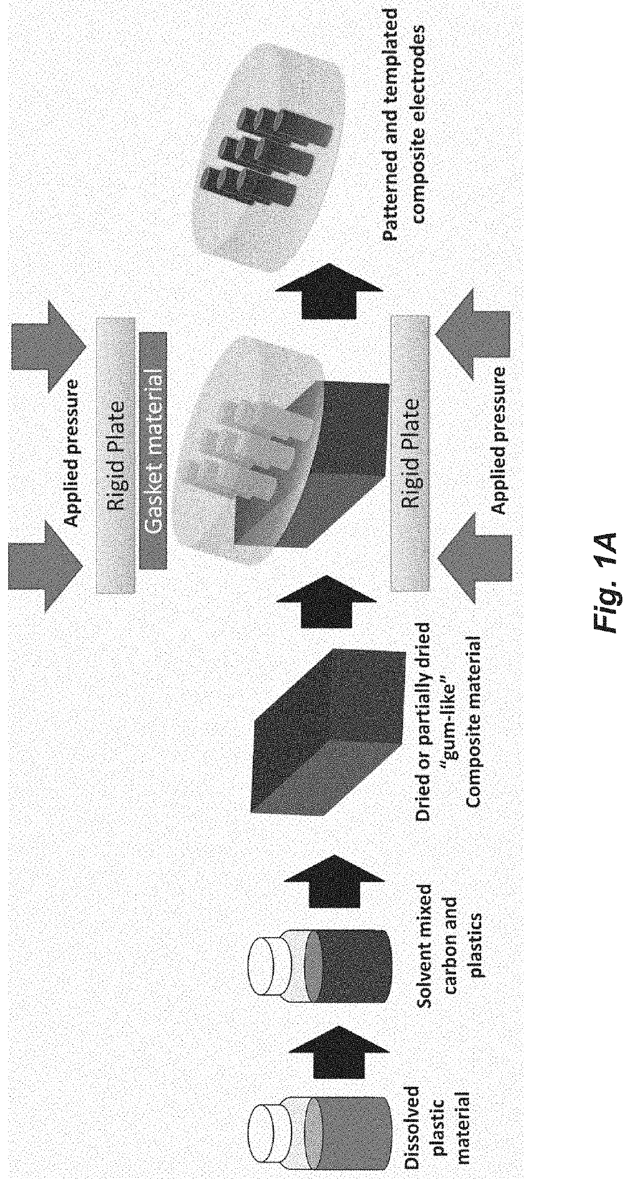
[0130]A thermoplastic (e.g., PMMA) is dissolved using a mixing agent. This may be any solvent (e.g., dichloroethane), or combination of solvents, capable of thoroughly dissolving the plasti...
example 3
stic Solution Preparation
[0140]Small centimeter sized PMMA pieces (Optix, Plaskolite) were massed and placed in a vial, then mixed with dichloroethane typically in a ratio of ˜5 mL solvent to 1 gram of PMMA, and kept for a period of months as stock solutions. When using dichloroethane, the small pieces of PMMA dissolved in about 24 hours. Dichloroethane and chloroform were found to be aggressive solvents for dissolving PMMA, and acetone, ethyl acetate, and DMF were also effective solvents. Toluene, xylenes, and propylene carbonate (PC) could dissolve the PMMA, however, the process took longer than a week to fully dissolve. Once fully dissolved, carbon was added, and the solvent level was adjusted to achieve a uniform mixture. A consistency of viscous oil was found to be desirable for the solvent / PMMA / carbon mixtures. Before use, the mixture was vortex mixed for ˜3 min, in a 20 mL scintillator vial. If the mixture was too viscous, efficient mixing did not occur. Sonication was not us...
PUM
| Property | Measurement | Unit |
|---|---|---|
| Length | aaaaa | aaaaa |
| Length | aaaaa | aaaaa |
| Length | aaaaa | aaaaa |
Abstract
Description
Claims
Application Information