Current collector and preparation method thereof, battery electrode pole piece and preparation method thereof, and lithium battery

A technology for battery electrodes and current collectors is applied in the fields of current collectors with micro-nano structures and their preparation, battery electrode pole pieces and preparation fields, and can solve the problems of increased internal resistance, high cost, complicated manufacturing process, etc., and can prevent the battery volume Swelling, preventing uncontrolled growth, improving Coulombic efficiency

Active Publication Date: 2021-08-17
SOUTH UNIVERSITY OF SCIENCE AND TECHNOLOGY OF CHINA
View PDF2 Cites 0 Cited by
  • Summary
  • Abstract
  • Description
  • Claims
  • Application Information

AI Technical Summary

Problems solved by technology

[0004] However, these existing solutions have their own defects: the deposition of lithium on hollow carbon is uncontrollable, the position and shape of deposited lithium cannot be controlled, and the distribution is uneven
Polyimide coating cannot make fine structures, especially at the nanometer level, and it will hinder the diffusion of lithium ions and increase internal resistance
Using gold plating to guide the deposition of lithium is a complex and long-term process, which cannot achieve large-scale high-throughput production, and the cost is high
[0005] Therefore, the existing methods either cannot perform in-situ high-precision guided deposition at the fabricated pattern, or the fabrication process is complex and costly, and cannot be applied to large-scale industrial production

Method used


Image

  • Current collector and preparation method thereof, battery electrode pole piece and preparation method thereof, and lithium battery
  • Current collector and preparation method thereof, battery electrode pole piece and preparation method thereof, and lithium battery
  • Current collector and preparation method thereof, battery electrode pole piece and preparation method thereof, and lithium battery

Examples


Embodiment 1

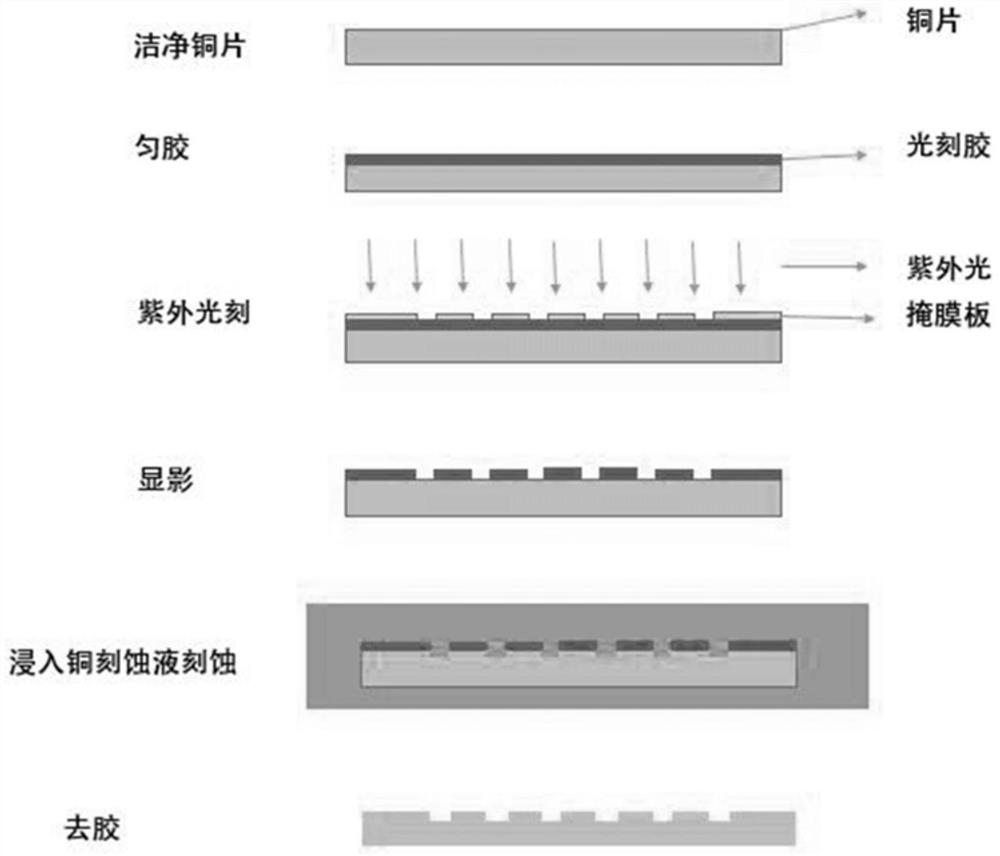
[0056] Fabrication of Current Collectors by Traditional Photolithography

[0057] Lithography: such as figure 1 As shown, select a copper sheet with a purity of 99.99% and a thickness of 100 microns. After cleaning it with acetone and IPA, spin-coat a layer of RJ-304 positive resist produced by Suzhou Ruihong Electronic Chemicals Co., Ltd. The thickness of the photoresist is about 1 μm. After pre-baking on a hot plate at 100° C. for 3 minutes, the copper sheet with the photoresist was exposed to ultraviolet rays with a designed pattern mask (a square with a side length of 25 μm). Put the exposed copper sheet into 3038 positive resist developing solution for development for about 30 seconds, blow it dry and then bake it on a hot plate at 100°C for 2 minutes.

[0058] Etching: put the above photoetched copper sheet into FeCl 3 Solution (concentration is 0.5mol / L) in etching 3 minutes, the pattern on the photoresist can be etched on the copper sheet, the place that photoresist...

Embodiment 2

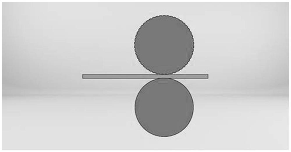
[0065] Fabrication of current collectors by nanoimprint lithography

[0066] Nanoimprinting: eg image 3 As shown, first, a layer of imprinting glue is sprayed on a clean copper sheet, and then a flexible template with a micro-nano structure (such as a nickel template) wrapped on a roller or a roller with a micro-nano structure itself is used, The embossing process is completed by transferring the graphic onto the embossing adhesive by roll-to-roll embossing. Wherein, the thickness of the nickel template is 100 microns, and the thickness of the copper sheet is about 20 microns.

[0067] Electrochemical corrosion: The above-mentioned imprinted copper sheet is firstly removed by reactive ion etching to remove the primer, and then clamped to the anode and immersed in the copper electroplating solution for electrochemical corrosion. The copper electroplating solution is copper sulfate and sulfuric acid, and the cathode is copper sheet , using electrochemical corrosion to make a ...

Embodiment 3

[0074] Preparation of electrode pole pieces by depositing lithium

[0075] The copper sheet with the micro-nano pattern etched in Example 1 is used as the current collector of the lithium metal battery, and the selective and precise deposition of lithium is carried out.

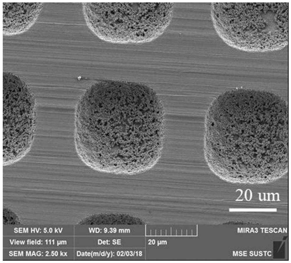
[0076] First, the etched Cu sheet with a micro-nano structure (using an array template with a 20-micron hole per hole as a substrate, etched for 5 minutes, the pit width after etching is 35 microns, and the depth is 9 microns) was used Wash with alcohol and acetone, then blow dry, and cut into discs with a diameter of 12 mm for later use.

[0077] Then, transfer the prepared pole piece to an argon atmosphere glove box (the content of water and oxygen is below 0.1ppm), all related operations are completed in the glove box, and lithium slices (12 mm diameter discs) are prepared in the glove box. , 0.5 mm thick), 2025 battery case, 0.5 micron stainless steel gasket, 1.2 micron stainless steel shrapnel, 1M LiTFS...


PUM

PropertyMeasurementUnit
thicknessaaaaaaaaaa
thicknessaaaaaaaaaa
densityaaaaaaaaaa

Abstract

The invention belongs to the field of lithium batteries, and discloses a current collector with a micro-nano structure and a preparation method thereof. The current collector has a pit and / or groove structure, and the surface of the pit and / or groove structure is covered with CuCl. The invention also discloses a battery electrode pole piece and a preparation method, as well as a lithium battery. The present invention uses CuCl to selectively deposit lithium and other metals in the electrolyte, and controls the deposition of lithium on the surface with a micro-nano structure, which can greatly reduce the internal stress of the lithium layer and alleviate the growth of dendrites. It can also enhance the binding force between lithium and the current collector, and there is no volume expansion problem relative to the entire current collector as an electrode. The deposition of lithium in pits and / or grooves, even if tiny dendrites appear, can provide space for them to grow, preventing their uncontrollable growth and battery volume expansion, causing potential safety hazards of battery short circuits, and greatly improving battery life. Coulombic efficiency.

Description

technical field [0001] The invention belongs to the field of lithium batteries, and in particular relates to a current collector with a micro-nano structure and a preparation method thereof, a battery electrode pole piece and a preparation method thereof, and a lithium battery. Background technique [0002] Lithium metal has a high mass specific capacity. Compared with the 372 mA h / g graphite negative electrode widely used in lithium-ion batteries, the mass specific capacity of lithium metal as a negative electrode material can reach 3860 mA h / g. And lithium metal has a lower density (0.534g / cm 3 ) and the lowest electrochemical potential (-3.040V). Due to the outstanding physical and chemical properties of lithium metal itself, lithium metal batteries have become an ideal battery material. In lithium metal batteries, a conductive substrate (such as copper sheet, stainless steel sheet) is often used as a current collector, and lithium is deposited on the current collector ...

Claims


Application Information

Patent Timeline
Patent Type & Authority Patents(China)
IPC IPC(8): H01M4/66H01M4/70H01M4/78H01M4/04H01M10/42H01M10/052
CPCY02E60/10
Inventor 卢周广程鑫李志强黄兴隆张腾飞
Owner SOUTH UNIVERSITY OF SCIENCE AND TECHNOLOGY OF CHINA
Why Eureka
Try Eureka