Preparation method of magnetic functionalized electrochemical microfluidic sensor
An electrochemical and sensor technology, applied in the field of preparation of magnetic functionalized electrochemical microfluidic sensors, can solve the problems of high experimental cost, low sensitivity, long detection period, etc., and achieve enhanced catalytic performance, high sensitivity, and easy operation. Effect
- Summary
- Abstract
- Description
- Claims
- Application Information
AI Technical Summary
Problems solved by technology
Method used
Image
Examples
Embodiment 1
[0037] Example 1 Preparation of Magnetic Functionalized Electrochemical Microfluidic Sensor
[0038] (1) Preparation of ferric oxide
[0039]Add 2.7 g of ferric chloride hexahydrate and 7.2 g of sodium acetate into 100 mL of ethylene glycol solution, stir magnetically to obtain a uniform yellow solution, transfer the solution to a polytetrafluoro autoclave, and react at 200 °C 8 h, washed with ethanol for 5 times by magnetic separation, and dried under vacuum at 60 °C;
[0040] (2) Preparation of molybdenum disulfide coated with ferric oxide
[0041] Disperse 0.1 g of iron ferric oxide nanoparticles in 50 mL of ultrapure water under ultrasonic conditions, then add 0.066 g of ammonium molybdate and 0.143 g of thiourea, sonicate for 20 minutes, and seal the solution in a polytetrafluoro autoclave , heated at 180°C for 12 h, washed with ethanol five times after magnetic separation, and dried in vacuum at 60°C;
[0042] (3) Preparation of gold-coated platinum core-shell nanopar...
Embodiment 2
[0051] Example 2 Preparation of microfluidic chip
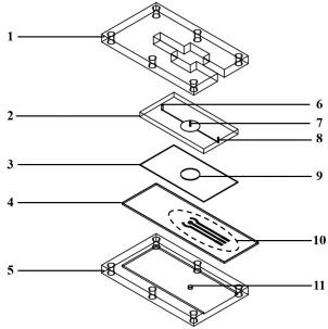
[0052] The microfluidic chip layer made of polydimethylsiloxane was prepared according to the designed pattern, the channel layer (2) and the microwell layer (3) were bonded by oxygen plasma treatment for 50 s, and the fixture layer was printed by a 3D printer , embedded in the groove (11) with a diameter of 3mm in the lower fixture (5), the fixture layer fixes the electrode layer (4) printed with the electrode system (10) and the microfluidic chip layer.
Embodiment 3
[0053] Example 3 Electrochemical microfluidic sensor for the detection of neuron-specific enolase
[0054] (1) Pass 20 µL of phosphate buffer solution with a pH value of 7.4 into the detection cell from the sample inlet;
[0055] (2) Connecting the three-electrode system (10) printed on the microfluidic chip to the electrochemical workstation;
[0056] (3) The electrochemical response of the standard solution of neuron-specific enolase at different concentrations was detected by chronoamperometry, and 5 mol / L was injected from the hydrogen peroxide inlet (7) at a flow rate of 10 μL / min when running for 60 s. Hydrogen peroxide solution, record the current intensity when running for 120 s, and draw the working curve;
[0057] (5) Use neuron-specific enolase solution of unknown concentration instead of neuron-specific enolase standard solution for detection, and calculate the content of neuron-specific enolase according to the obtained working curve.
PUM
| Property | Measurement | Unit |
|---|---|---|
| diameter | aaaaa | aaaaa |
Abstract
Description
Claims
Application Information
 - R&D
- Intellectual Property
- Life Sciences
- Materials
- Tech Scout
- Unparalleled Data Quality
- Higher Quality Content
- 60% Fewer Hallucinations
Browse by: Latest US Patents, China's latest patents, Technical Efficacy Thesaurus, Application Domain, Technology Topic, Popular Technical Reports.
© 2025 PatSnap. All rights reserved.Legal|Privacy policy|Modern Slavery Act Transparency Statement|Sitemap|About US| Contact US: help@patsnap.com

