Supercritical fluid production of graphene-based supercapacitor electrode from coke or coal

a supercapacitor electrode and graphene-based technology, which is applied in the direction of single-layer graphene, cell components, batteries, etc., to achieve the effect of reducing the thickness of a graphene sheet or the number of graphene planes

Active Publication Date: 2021-09-14
NANOTEK INSTR GRP LLC
View PDF105 Cites 4 Cited by
  • Summary
  • Abstract
  • Description
  • Claims
  • Application Information

AI Technical Summary

Benefits of technology

[0052]In certain embodiments, the process further comprises a procedure of essentially repeating step (a) and step (b), which include (i) subjecting the isolated graphene sheets to a supercritical fluid at a second temperature and a second pressure for a second period of time in a pressure vessel and then (ii) rapidly depressurizing the fluid at a fluid release rate sufficient for effecting further exfoliation and separation of graphene sheets (to further reduce the thickness of a graphene sheet or the number of graphene planes in a graphene sheet). As a result, one can obtain essentially all few-layer graphene or all single-layer graphene sheets. The second temperature can be the same as or different from the first temperature. The second pressure can be the same as or different from the first pressure.

Problems solved by technology

However, there are several serious technical issues associated with current state-of-the-art supercapacitors:(1) Experience with supercapacitors based on activated carbon electrodes shows that the experimentally measured capacitance is always much lower than the geometrical capacitance calculated from the measured surface area and the width of the dipole layer.
This disappointing performance is related to the presence of micro-pores (<2 nm, mostly <1 nm) and ascribed to inaccessibility of some pores by the electrolyte, wetting deficiencies, and / or the inability of a double layer to form successfully in pores in which the oppositely charged surfaces are less than about 1-2 nm apart.
In activated carbons, depending on the source of the carbon and the heat treatment temperature, a surprising amount of surfaces can be in the form of such micro-pores that are not accessible to liquid electrolyte.(2) Despite the high gravimetric capacitances at the electrode level (based on active material weights alone) as frequently claimed in open literature and patent documents, these electrodes unfortunately fail to provide energy storage devices with high capacities at the supercapacitor cell or pack level (based on the total cell weight or pack weight).
This is due to the notion that, in these reports, the actual mass loadings of the electrodes and the apparent densities for the active materials are too low.
The low mass loading is primarily due to the inability to obtain thicker graphene-based electrodes (thicker than 100 μm) using the conventional slurry coating procedure.
Contrarily, thicker electrodes tend to become extremely brittle or of poor structural integrity and would also require the use of large amounts of binder resin.
These problems are particularly acute for graphene material-based electrodes.
It has not been previously possible to produce graphene-based electrodes that are thicker than 100 μm and remain highly porous with pores remaining fully accessible to liquid electrolyte.
The low areal densities and low volume densities (related to thin electrodes and poor packing density) result in relatively low volumetric capacitances and low volumetric energy density of the supercapacitor cells.
However, individual nano graphene sheets have a great tendency to re-stack themselves, effectively reducing the specific surface areas that are accessible by the electrolyte in a supercapacitor electrode.
However, these pores or inter-graphene spacings must also be sufficiently small to ensure a large tap density (hence, large capacitance per unit volume or large volumetric energy density).
Unfortunately, the typical tap density of graphene-based electrode produced by the conventional process is less than 0.3 g / cm3, and most typically 3.
Another major technical barrier to using graphene sheets as a supercapacitor electrode active material is the challenge of forming a thick active material layer onto the surface of a solid current collector (e.g. Al foil) using the conventional graphene-solvent slurry coating process.
In addition, any graphene electrode prepared in this manner that is thicker than 50 μm is brittle and weak.
There has been no effective solution to these problems.
There are several major problems associated with this conventional chemical production process:(1) The process requires the use of large quantities of several undesirable chemicals, such as sulfuric acid, nitric acid, and potassium permanganate or sodium chlorate.(2) The chemical treatment process requires a long intercalation and oxidation time, typically 5 hours to five days.(3) Strong acids consume a significant amount of graphite during this long intercalation or oxidation process by “eating their way into the graphite” (converting graphite into carbon dioxide, which is lost in the process).
It is not unusual to lose 20-50% by weight of the graphite material immersed in strong acids and oxidizers.(4) Both heat- and solution-induced exfoliation approaches require a very tedious washing and purification step.
The process must be carefully conducted in a vacuum or an extremely dry glove box environment since pure alkali metals, such as potassium and sodium, are extremely sensitive to moisture and pose an explosion danger.
This process is not amenable to the mass production of NGPs.
However, these processes are not suitable for mass production of isolated graphene sheets for composite materials and energy storage applications.
This is a slow process that thus far has produced very small graphene sheets.
The purification of graphite ore involves the use of large amounts of undesirable chemicals.
As of today, the graphene, as an industry, has yet to emerge mainly due to the extremely high graphene costs that have thus far prohibited graphene-based products from being widely accepted in the marketplace.

Method used


Image

  • Supercritical fluid production of graphene-based supercapacitor electrode from coke or coal
  • Supercritical fluid production of graphene-based supercapacitor electrode from coke or coal
  • Supercritical fluid production of graphene-based supercapacitor electrode from coke or coal

Examples


example 1

n of Isolated Graphene Sheets from Milled Coal-Derived Needle Coke Powder

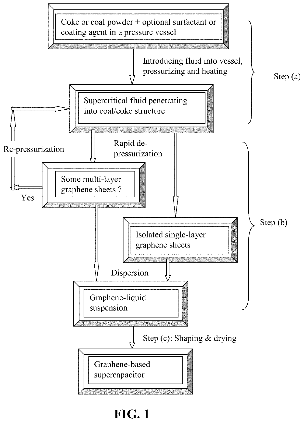
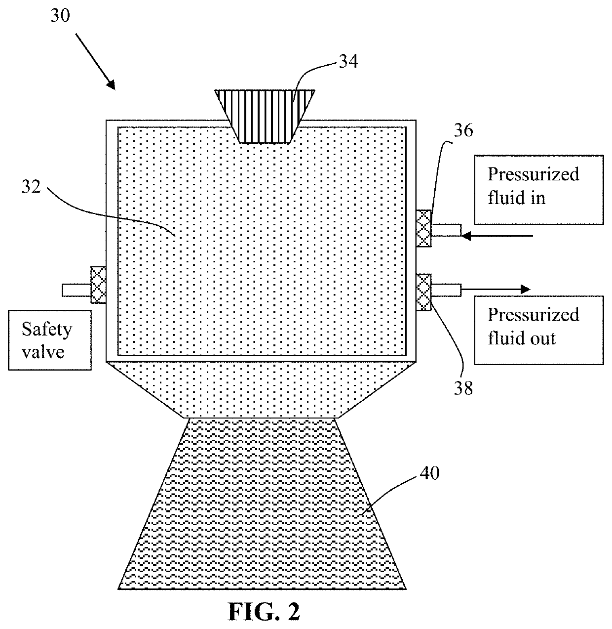
[0134]Needle coke, milled to an average length 2 by way of piping means and controlled or regulated by valves. A heating jacket was wrapped around the vessel to achieve and maintain the critical temperature of carbon dioxide. High-pressure carbon dioxide was introduced into the vessel and maintained at approximately 1,100 psig (7.58 MPa). Subsequently, the vessel was heated to about 70° C. at which the supercritical conditions of carbon dioxide were achieved and maintained for about 3 hours, allowing CO2 to diffuse into inter-graphene spaces and / or the amorphous zones between graphene domains. Then, the vessel was immediately depressurized “catastrophically” at a rate of about 3 milliliters per second. This was accomplished by opening a connected blow-off valve of the vessel. As a result, exfoliated graphene layers were formed, which were found to have an average thickness less than 1.0 nm. Various samples were...

example 4

n of Isolated Graphene Sheets and Graphene Electrodes from Milled Petroleum Needle Coke Powder

[0148]Needle coke, milled to an average length 2 gas through pipe means as in Example 1. The pressure at approximately 8.5 MPa was maintained while the vessel was heated to about 70° C. to achieve a supercritical condition of carbon dioxide. This intercalation process was conducted for about 1 hour, followed by a sudden depressurization to the ambient pressure. The resulting expanded / exfoliated structure after the initial cycle was investigated using AFM, SEM, and BET measurements. The NGPs obtained were found to have an average thickness of 1.3 nm. The intercalation and exfoliation steps were repeated for another cycle and the resulting graphene sheets are all single-layer or double-layer.

[0149]A small amount of polyethylene oxide (PEO / graphene ratio=1 / 20 by weight) was added into the water suspension containing graphene sheets after mechanical shearing. The suspension was extruded into fi...

example 5

Electrodes from Milled Lignite Coal Powder

[0150]In one example, samples of two grams each of lignite coal were milled down to an average diameter of 25.6 μm. The powder samples were subjected to ethanol-based supercritical fluid treatments: 514° K and 6.4 MPa, followed by rapid de-pressurization. The resulting graphene sheets exhibit a thickness ranging from single-layer graphene sheets to 3-layer graphene sheets based on SEM and TEM observations. The resulting suspension was cast into films and then heat-treated at 100° C. for 1 hour and then 350° C. for 4 hours to produce sheets of graphene foam. The specific capacitance of these sheets of foam was found to be 175-210 F / g.

Example 6: Production of Isolated Graphene Sheets and Graphene Electrodes from Anthracite Coal

[0151]Taixi coal from Shanxi, China was used as the starting material for the preparation of isolated graphene sheets and graphene electrodes. The raw coal was ground and sieved to a powder with an average particle size ...


PUM

PropertyMeasurementUnit
specific surface areaaaaaaaaaaa
thicknessaaaaaaaaaa

Abstract

Provided is a process for producing a graphene-based supercapacitor electrode from a supply of coke or coal powder, comprising: (a) exposing this powder to a supercritical fluid for a period of time in a pressure vessel to enable penetration of the supercritical fluid into internal structure of the coke or coal; wherein the powder is selected from petroleum coke, coal-derived coke, meso-phase coke, synthetic coke, leonardite, anthracite, lignite coal, bituminous coal, or natural coal mineral powder, or a combination thereof; (b) rapidly depressurizing the supercritical fluid at a fluid release rate sufficient for effecting exfoliation and separation of the coke or coal powder to produce isolated graphene sheets, which are dispersed in a liquid medium to produce a graphene suspension; and (c) shaping and drying the graphene suspension to form the supercapacitor electrode having a specific surface area greater than 200 m2 / g.

Description

FIELD OF THE INVENTION[0001]The present invention relates to a process for producing a graphene-based supercapacitor electrode directly from natural coal or coal derivatives (e.g. needle coke) using supercritical fluid.BACKGROUND[0002]Electrochemical capacitors (ECs), also known as ultracapacitors or supercapacitors, are being considered for uses in hybrid electric vehicles (EVs) where they can supplement a battery used in an electric car to provide bursts of power needed for rapid acceleration, the biggest technical hurdle to making battery-powered cars commercially viable. A battery would still be used for cruising, but supercapacitors (with their ability to release energy much more quickly than batteries) would kick in whenever the car needs to accelerate for merging, passing, emergency maneuvers, and hill climbing. The EC must also store sufficient energy to provide an acceptable driving range. To be cost-, volume-, and weight-effective compared to additional battery capacity th...

Claims


Application Information

Patent Timeline
Patent Type & Authority Patents(United States)
IPC IPC(8): H01M4/1393H01G11/42C01B32/19H01G11/44H01G11/26C04B35/528H01G11/36H01M4/62H01M4/133C04B35/524H01G11/24H01G11/32H01G11/86
CPCH01M4/1393C01B32/19C04B35/524C04B35/528H01G11/24H01G11/26H01G11/32H01G11/36H01G11/42H01G11/44H01G11/86H01M4/133H01M4/625C04B2235/425C04B2235/5292H01M2220/20Y02E60/13Y02P20/54C01B2204/02C01B2204/04C01B2204/22C01B2204/32C01B32/192C01B32/194Y02E60/10
Inventor ZHAMU, ARUNAJANG, BOR Z.
Owner NANOTEK INSTR GRP LLC
Why Eureka
Try Eureka