Intumescent fire retardant composition and method of manufacture thereof

a fire retardant composition and intumescent technology, applied in the field of intumescent composition and intumescent additive mixture, can solve the problems of intumescent coating, long process cycle, weak sponge with limited life, etc., and achieve the effect of reducing smoke, improving processability of intumescent composition, and reducing smok

Inactive Publication Date: 2003-08-21
APTIV TECH LTD
View PDF0 Cites 28 Cited by
  • Summary
  • Abstract
  • Description
  • Claims
  • Application Information

AI Technical Summary

Benefits of technology

0032] The intumescent composition can also optionally comprise additives aimed at reducing smoke when the intumescent composition burns, for example, metal oxides such as titanium dioxide, and cobalt and manganese organic compounds. In addition to reducing smoke, these smoke reducing additives also improve the processability of the intumescent composition during formation by reducing the torque required for melt processing. Moreover, the aesthetic qualities of articles molded from the intumescent composition are enhanced. These smoke reducing additives also provide added flame retardancy to the formulation and serve to further enhance the formation of char.
0033] The intumescent composition may optionally contain cross-linking agents. Generally, these cross-linking agents are small concentrations of free radical-generating peroxides, such as dicumyl peroxide, and cross-linking co-agents, such as trimethylolpropane trimethacrylate (TMPT), and the like, as well as combinations comprising at least one of the foregoing cross-linking agents and coagents. These agents improve the rigidity of the intumescent composite material, especially upon exposure to fire. Dicumyl peroxide is commercially available for example, under the trademark DICUP 40KE.RTM. from Hercules Inc., Wilmington, Del., and TMPT is available as a liquid or adsorbed to the surface of silica powder SARET 500.RTM. from Sartomer Company, Inc., Exton, Pa.

Problems solved by technology

Reactions occur within the intumescent composition so that when the composition is heated to beyond a specific activation temperature, components (such as the polyhydric alcohol, ammonium hydrogen phosphate or hydrated magnesia) within the composition are decomposed, thereby generating water, carbon dioxide, ammonia, and / or other heat absorbing gases that do not readily support combustion.
Intumescent coatings however, require a lengthy and complicated process for their application to a surface.
When these coatings become intumescent after exposure to elevated temperatures, the coatings are transformed into a weak sponge with a limited life.
The additional hardware and the use of adhesives, adds to the complexity and costs associated with this use.

Method used


Image

  • Intumescent fire retardant composition and method of manufacture thereof
  • Intumescent fire retardant composition and method of manufacture thereof

Examples


examples 2-3

[0050] In these examples, the compositions of which are shown in Table 3, the synergistic effect of antimony oxide and intercalated graphite is demonstrated. In Example 2, the polymeric resin comprises HDPE, whereas in Example 3, the polymeric resin is a blend of HDPE and polypropylene. The HDPE utilized in Examples 2 and 3 is WR 201, a high viscosity polyethylene obtained from Atofina, Paris, France. The intumescent compositions were tested in accordance with Underwriters Laboratory vertical flammability test UL-94. The rating was V -0 for both Examples 2 and 3, indicating that the sample self-extinguished after removal of the flame. Moreover no after glow, and no melt dripping was observed.

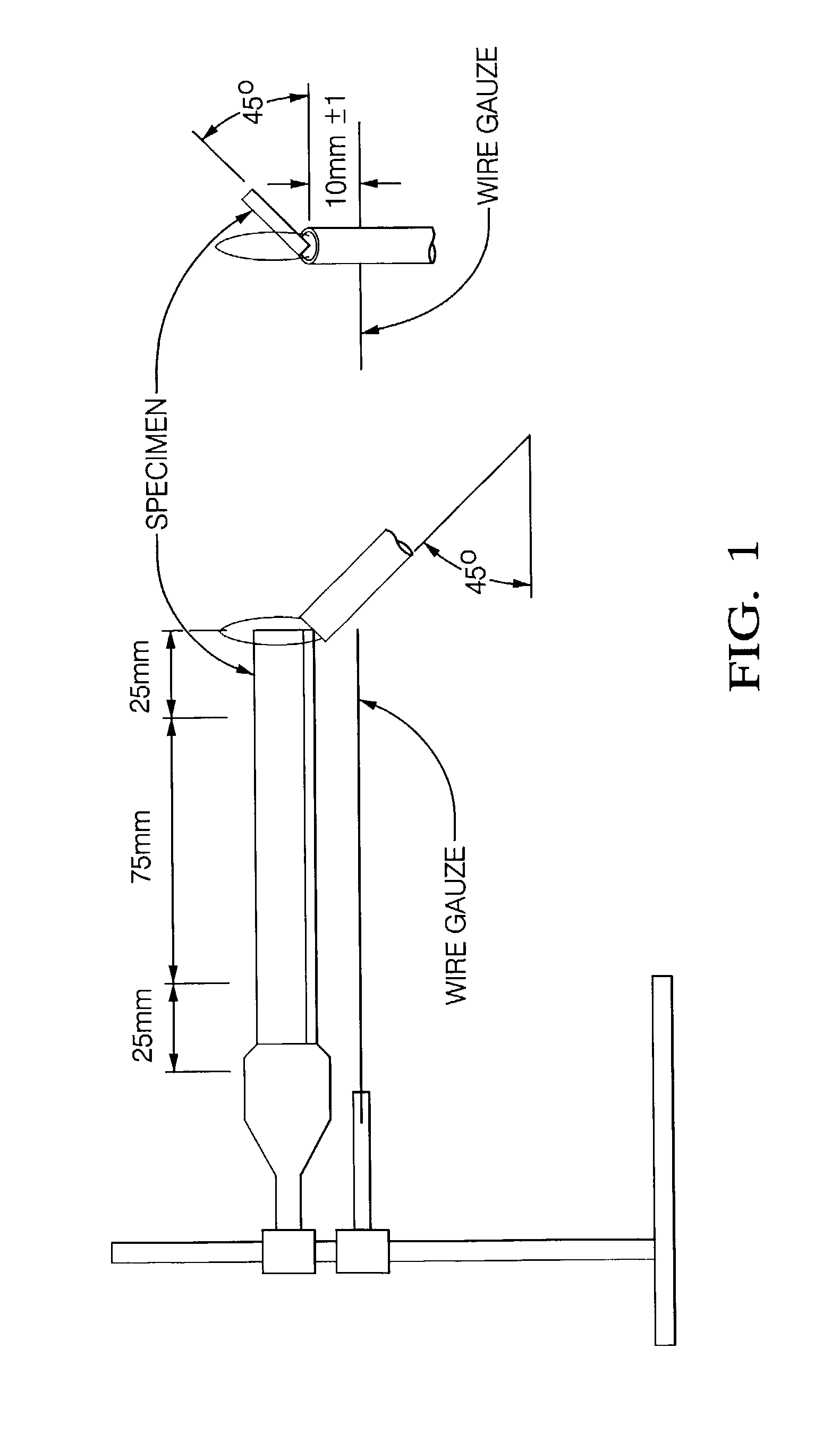
[0051] In this tests a vertically oriented bar (125 mm long, 13 mm wide, and 3 mm thick) was exposed to a Bunsen burner flame for ten seconds. If the sample self extinguished, burn time (t1) was noted. The sample was then exposed to the flame for an additional 10 second period. If it again self-...

examples 4-7

[0052] In these examples shown in Table 4, the melt viscosity of the polymer, e.g., polyethylene, utilized in the intumescent compositions was varied. The melt viscosity of a polymeric resin is measured by using the melt index, which is the number of grams of molten polymer that passes through a capillary when the polymer is heated to a certain temperature above its melting point and a load is applied to the polymer to push it through a capillary. Generally, for viscous polymers a load of 21,600 grams is needed in order to push the molten polymer through the capillary, while for lower viscosity polymers a load of 2,160 grams is used. In Example 4, a blow molding grade of polyethylene, WR 201 B, made by Atofina, having a melt index of 8 (at a load of 21,600 grams) was utilized. In Example 5, the polyethylene utilized was K-44-24-122, a medium melt viscosity polymer supplied by Solvay, Houston, Tex. The K-44-24-122 had a melt index of 0.35g / 10 minutes measured at 190.degree. C. and a ...

example 8

[0053] In this example, polypropylene obtained from Exxon Chemical Company, Houston, Tex. was employed in the intumescent composition. The polypropylene had a melt index of 3.1 grams / 10 minutes at 230.degree. C. and a load of 2,160 grams. The composition and the properties of Example 8 are shown in Table 5, where it can be seen that the material has a UL-94 rating of V -0 and passes the fire shield flammability test.

5 TABLE 5 Example 8 Components (wt %) Chlorinated Polyethylene 19 (CPE 3615) Polypropylene 45 Chlorowax 5 (PAROIL 145) Magnesium hydroxide 15 (MAGSHIELD) Distearylthiodipropionate 0.5 (DSTDP) Hindered phenol 0.5 (WINGSTAY L) Antimony Oxide 5 (FIRESHIELD) Graphite Flake 5 (DXN 3579) Glass fiber 5 Properties UL-94 Classification 94V-0 (1 sec) Fire shield flammability Passed test Tensile Modulus @ 50% 14.14 strain (MPa) Tensile strength (MPa) 15.65 Strain at Break (%) 51.6 Flexural Modulus (MPa) 1177


PUM

PropertyMeasurementUnit
wt %aaaaaaaaaa
temperaturesaaaaaaaaaa
diametersaaaaaaaaaa

Abstract

One embodiment of an intumescent composition comprises a halogenated polymer, antimony oxide, and intercalated graphite, while one embodiment of an intumescent additive mixture comprises antimony oxide and intercalated graphite. One embodiment of the method of making an intumescent composition comprises melt blending a halogenated polymer with antimony oxide, and intercalated graphite.

Description

[0001] This application is a Continuation-in-Part of U.S. Ser. No. 10 / 055,112, filed Jan. 23, 2002, and claims priority to U.S. Provisional Application No. 60 / 351,137 filed Jan. 23, 2002, the entire contents of which are incorporated herein by reference.[0002] This disclosure relates to fire retardant materials, and, more particularly, to moldable intumescent compositions. Intumescent compositions are generally fire retardant composite compounds that swell and form ceramic-like sponges when exposed to the high temperatures. Intumescent compositions can be applied in the form of coatings or paints or they may be formed into mat-like structures that may be placed within or around an apparatus exposed to or operating under high temperatures.[0003] Intumescent compositions are generally used on the wall surfaces of buildings, ships, aircraft, motor vehicles, or other vessel. The nature of the composition allows its thickness to be kept at a minimum until it is activated by high temperat...

Claims


Application Information

Patent Timeline
Patent Type & Authority Applications(United States)
IPC IPC(8): C08K3/00C08K5/00C08L23/06C08L23/28C09D5/18
CPCC08K3/0008C08K5/0008C08L23/06C08L23/286C08L2312/00C09D5/185C08L23/28C08L2666/04C08K3/01
Inventor ABU-ISA, ISMAT A.MARCZEWSKI, RICHARD W.WILLIAMS, MARK M.
Owner APTIV TECH LTD
Why Eureka
Try Eureka