Manufacturing method for transparent and conductive coatings

a manufacturing method and electro-conductive coating technology, applied in the direction of oxide conductors, non-metal conductors, conductors, etc., can solve the problems of difficult to obtain transparent electro-conductive coatings of low prices, low reproducibility and yield, and high cost, and achieve stable arcs. , the effect of easy heating of metal wires

Inactive Publication Date: 2005-09-15
WU L W +1
View PDF25 Cites 6 Cited by
  • Summary
  • Abstract
  • Description
  • Claims
  • Application Information

AI Technical Summary

Benefits of technology

[0027] In the first step, the method begins with feeding a wire or rod of either a pure metal or metal alloy onto an electrode (referred to as a consumable electrode) in the upper portion of a coating chamber. A non-consumable electrode is disposed in the vicinity of the consumable electrode. The proximal ends of the two electrodes are inclined at an angle relative to each other. The opposite ends of these two electrodes are connected to a high-current power source. In the second step, the high currents strike an ionized arc between the proximal ends of the two electrodes in the presence of a working gas. The ionized arc heats and vaporizes the wire or rod tip to form nano-sized metal vapor clusters. While the leading tip of a wire or rod is being consumed by the arc, the wire or rod is continuously or intermittently fed into an arc zone. This, along with the constant supply of a work...

Problems solved by technology

The first method requires the utilization of expensive devices and its reproducibility and yield are low.
Furthermore, the procedure is tedious and time-consuming, typically involving the preparation of fine oxide particles, compaction and sintering of these fine particles to form a target, and then laser- or ion beam-sputtering of this target in a high-vacuum environment.
Therefore, it was difficult to obtain transparent electro-conductive coatings that are of low prices.
The electro-conductive film formed on the support by the second method tends to have some gaps remaining between the ultra-fine particles thereon so that light scatters on the film, resulting in poor optical properties.
However, the glass-...

Method used


Image

  • Manufacturing method for transparent and conductive coatings
  • Manufacturing method for transparent and conductive coatings
  • Manufacturing method for transparent and conductive coatings

Examples


example 1

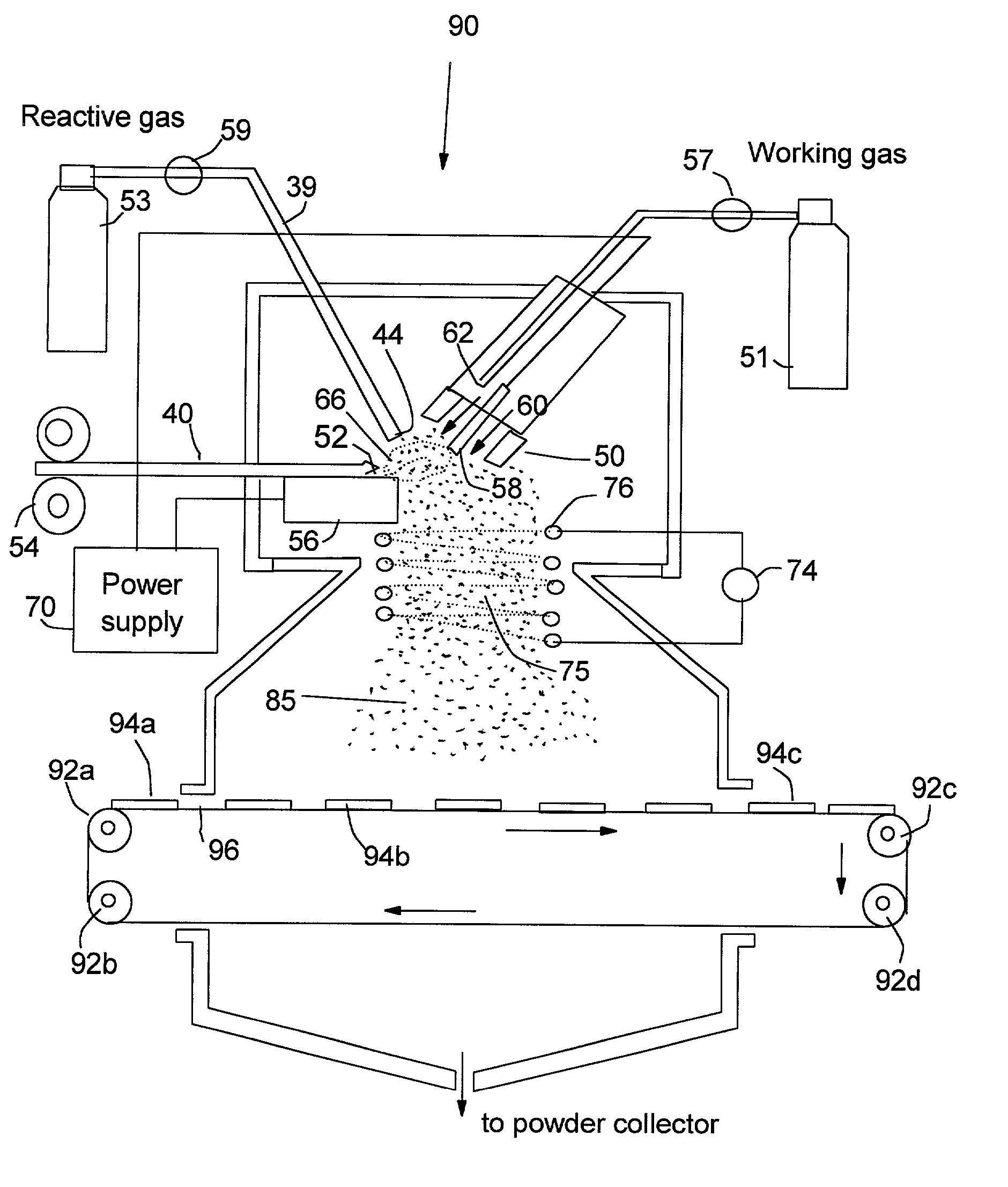
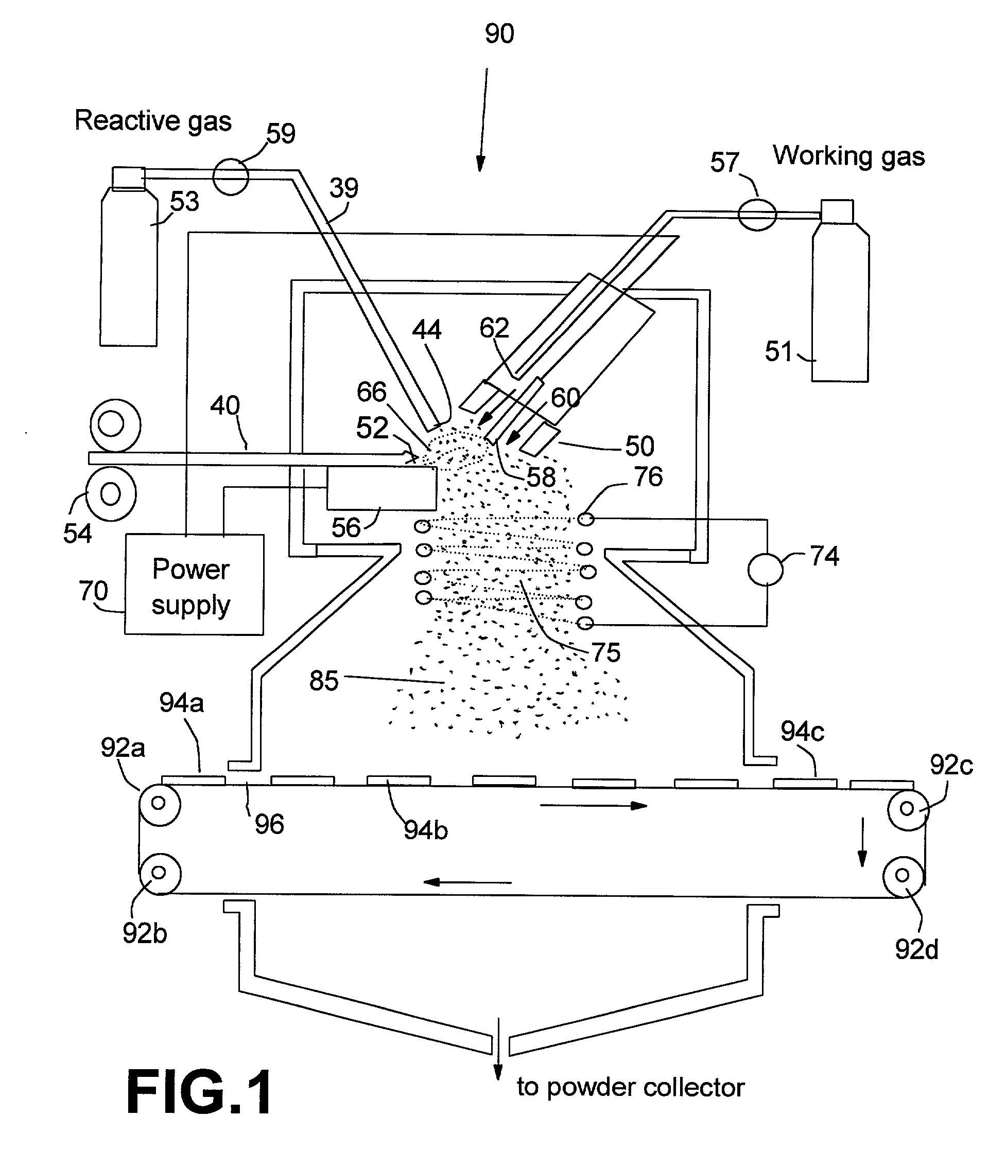
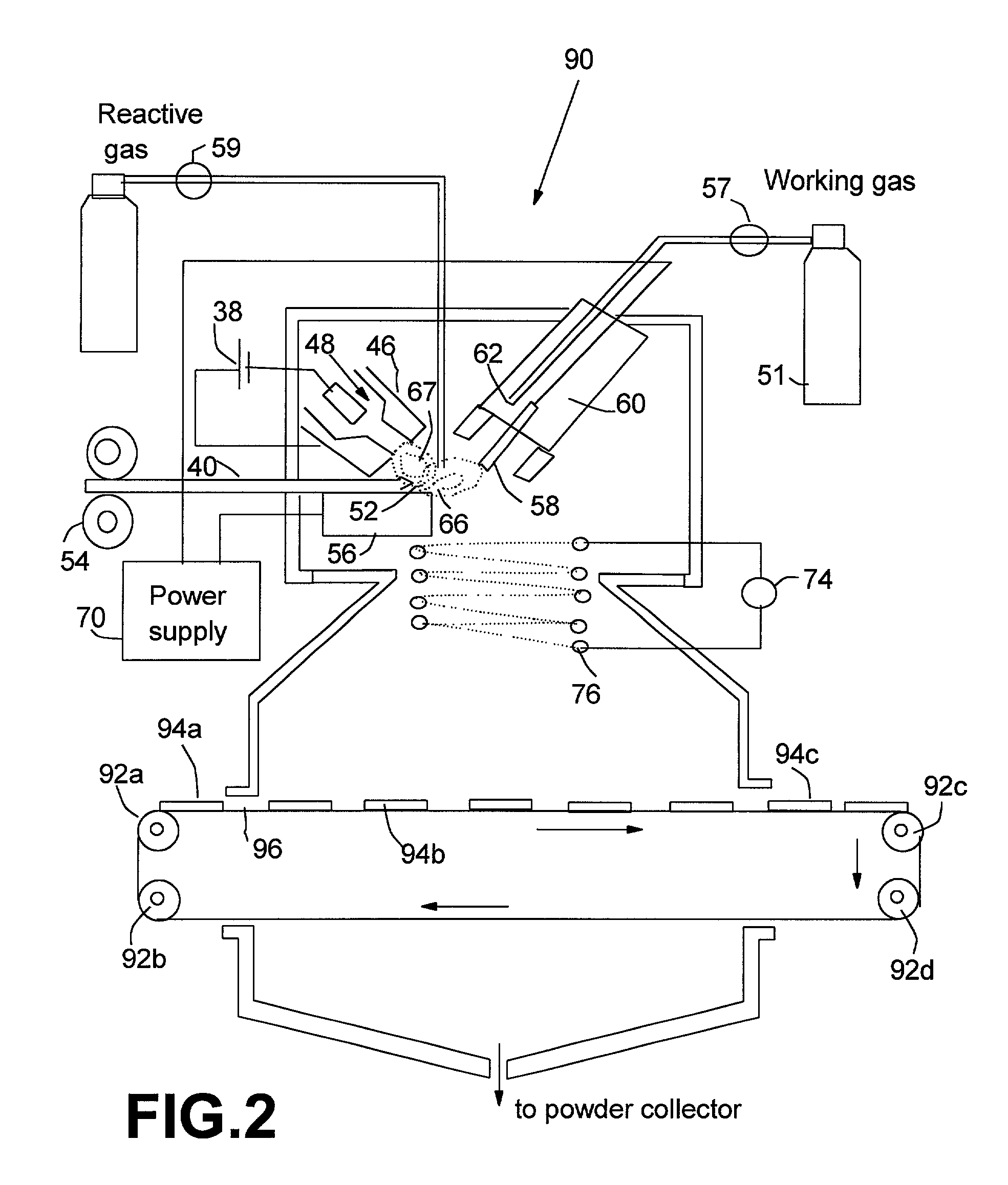
[0068] An Al—Cu metal alloy rod of ⅛ inch diameter was used as a precursor material disposed on a top horizontal surface of the consumable electrode. The non-consumable electrode, which was used as a cathode, was a material consisting of 2% thoriate dispersed in a matrix of W. This electrode was shielded by 25-100 cfh of a working gas of argon combined with 5-100% nitrogen and / or 5-50% hydrogen. The current of the arc was adjusted between approximately 100 and 450 amps, which generated an arc tail flame 1-4 inches long that evaporated the precursor material. The arc created a stream of metal vapor clusters of 1-200 g / hr while an oxygen flow of 10-1000 cfh was injected into the tail flame to form mixed oxide vapor clusters of the starting metal alloy. These vapor clusters were directed to deposit on a glass substrate. The micro-structure of the resulting coatings was typically characterized by grain sizes in the range of 1-50 nm. The room-temperature p-type conductivity of these coat...

example 2

[0069] A powder mixture of 70% tin and 30% indium was compounded into a rod ½ diameter by pressing and sintering. The rod was electrically conductive and used as a precursor material in the consumable electrode or anode. The same cathode as in Example 1 was used and shielded by approximately 50 cfh of a working gas of argon in combined with 5-50% nitrogen or 5-50% hydrogen. The current of the arc ranged from 100-450 amps. The precursor material was evaporated by the arc to produce a vapor of 1-200 g / hr in a plasma tail flame created by the transferred arc. Concurrently, 10-500 cfh oxygen was injected into the tail flame to produce complete indium-tin oxide vapor clusters. These oxide clusters were directed to deposit onto a glass. The coatings were found to be nano-grained with grain sizes of 5-35 nm. The room-temperature n-type conductivity of these coatings were approximately 5.5×10³ S / cm.

example 3

[0070] The process of Example 2 was repeated except that tin was replaced by zinc. The resulting indium-zinc oxide coating exhibited grain sizes in the range of 3 to 25 nm. The room-temperature n-type conductivity of these coatings were approximately 3.5×10 3 S / cm.


PUM

PropertyMeasurementUnit
Temperatureaaaaaaaaaa
Electrical conductivityaaaaaaaaaa
Electrical conductoraaaaaaaaaa

Abstract

A method for producing a transparent, electrically conductive coating onto a substrate. The method includes the steps of (a) providing an ionized arc nozzle which includes a consumable electrode, a non-consumable electrode, and a working gas flow to form an ionized arc between the two electrodes, wherein the consumable electrode provides a metal material vaporizable from the consumable electrode by the ionized arc; (b) operating the arc nozzle to heat and at least partially vaporize the metal material for providing a stream of nanometer-sized metal vapor clusters into a chamber in which the substrate is disposed; (c) introducing a stream of oxygen-containing gas into the chamber to impinge upon the stream of metal vapor clusters and exothermically react therewith to produce substantially nanometer-sized metal oxide clusters; and (d) directing the metal oxide clusters to deposit onto the substrate for forming the coating.

Description

FIELD OF THE INVENTION [0001] The present invention is directed to a method for producing an optically transparent and electrically conductive coating on a substrate. The coated substrate is most suitable for use as electrodes in liquid crystal displays (LCD), electro-luminescence displays, anti-static shields, and electromagnetic wave shields, etc. BACKGROUND OF THE INVENTION [0002] The following U.S. patents represent the state of the art of the manufacturing methods and apparatus for optically transparent and electrically conductive coatings or substrates: [0003] 1. P. Vilato, et al., “Product with glass substrate carrying a transparent conductive layer containing zinc and indium and process for obtaining it,” U.S. Pat. No. 5,206,089 (Apr. 27, 1993). [0004] 2. M. Sakakibara, et al., “Sputtering target and method for producing same,” U.S. Pat. No. 5,435,826 (Jul. 25, 1995). [0005] 3. M. Kawata, et al., “Electroconductive substrate and method for forming same,” U.S. Pat. No. 5,763,...

Claims


Application Information

Patent Timeline
IPC IPC(8): H01B1/08
CPCC23C14/0021C23C14/086H01B1/08C23C14/56C23C14/325
Inventor WU, L. W.HUANG, WEN-CHIANG
Owner WU L W
Why Eureka
Try Eureka