Electromagnetic noise suppressor, article with electromagnetic noise suppressing function, and their manufacturing methods

a technology of electromagnetic noise suppression and suppressor, which is applied in the direction of inductance, transportation and packaging, non-metallic protective coating application, etc., can solve the problems of insufficient robustness and flexibility, increase in noise, and inability to say weight reduction has been achieved, etc., to achieve easy manufacturing, easy to manufacture, and high electromagnetic noise suppressing

Inactive Publication Date: 2006-04-20
SHIN-ETSU POLYMER CO LTD
View PDF12 Cites 100 Cited by
  • Summary
  • Abstract
  • Description
  • Claims
  • Application Information

AI Technical Summary

Benefits of technology

[0026] The electromagnetic noise suppressor of the present invention includes a base material containing a binding agent and a composite layer formed by integrating the binding agent that is a part of the base material and a magnetic material. This electromagnetic noise suppressor has high electromagnetic noise suppressing effect in the sub-microwave band and enables it to reduce the space requirement and weight.
[0027] The composite layer is desirably a layer formed by physical vapor deposition of a magnetic material on the base material surface. In such a composite layer, the magnetic material is dispersed in the binding agent so that the magnetic material and the binding agent are integrated to provide high electromagnetic noise suppressing effect. The composite layer does not contain impurity ions so that there is no possibility of damage to the electronic circuit by the impurity ions.
[0028] The electromagnetic noise suppressor of the present invention has maximum transmission attenuation of electromagnetic radiation per unit thickness of the composite layer preferably in a range from −0.5 to −500 dB / μm. In such a composite layer, the magnetic material is dispersed in the binding agent so that the magnetic material and the binding agent are integrated to provide high electromagnetic noise suppressing effect.

Problems solved by technology

However, as such apparatuses become popular, concerns have been increasing on the problems related to the electromagnetic interference such as malfunctions of the apparatus that emit electromagnetic radiation or other apparatuses and health threats to the human body.
Therefore, it cannot be said that weight reduction has been achieved.
It is also not sufficiently robust and flexible since its content of organic binding agent is small.
Moreover, the flaked powder of soft magnetic material is expensive because it requires tedious processes to form the soft magnetic material in flakes and making the surface not electrically conductive.
The electromagnetic radiation absorbing material that uses the flaked powder of soft magnetic material in a large amounts also is expensive and cannot satisfy the needs of industry.
Since the organic film which has high heat resistance is expensive, the electromagnetic radiation absorbing material that uses it is also expensive.
Moreover, even when the ultra-fine crystal of ferromagnetic material is formed on the organic film having high heat resistance, there is a significant difference in the thermal expansion coefficient between the organic film and the ceramic phase that causes cracks, resulting in a material far from being flexible or tough.
However, thickness of the ferromagnetic layer of this electromagnetic noise suppressor is from 3 to 11 μm and power loss of the electromagnetic noise suppressor at 1 GHz is about 0.2 even when formed with a large thickness, resulting in insufficient electromagnetic noise suppressing effect in low frequency portion of the sub-microwave band.
When the thickness of the ferromagnetic material increases, sufficient robustness and flexibility cannot be achieved since the ferrite layer formed on the polyimide is hard and does not contain organic binding agent.
Moreover, since it is made in a wet process, it requires tedious processes such as removal of impurities and drying, and does not satisfy the needs of industry.
However, this electromagnetic noise suppressor has electromagnetic radiation absorbing property similar to that of the conventional electromagnetic noise suppressor made in a sheet 50 μm thick by dispersing the fine particles of flake-shaped metal in the organic binding agent and power loss of about 0.2 at 1 GHz, resulting in insufficient electromagnetic noise suppressing effect in the effective frequency band.
Also, it is necessary to apply heat treatment in order to form the ultra-fine crystals of ferromagnetic material in the ceramic phase and a micro slit must be formed by photolithography or by means of a dicing saw in order to increase the resistivity of the thin magnetic film, making the process tedious.
Also because it is a thin ceramic film, it is prone to cracks, resulting in a material which is far from being flexible or robust.
As a result, the electromagnetic radiation absorbing material becomes heavy because the electromagnetic radiation absorbing layer has a high specific gravity and is thick.
Also there has been a problem in that it is difficult to reduce the space requirement because the electromagnetic radiation absorbing layer is provided on the support material and is thick.
Moreover, since the soft magnetic material powder is a metal powder, it can easily generate heat and ignite.
Also, because the electromagnetic radiation absorbing material consists mostly of soft magnetic material powder with a small proportion occupied by the polymer binding agent, it is less flexible and is brittle.
As a result, the electromagnetic radiation absorbing material is heavy because the electromagnetic radiation absorbing layer has a high specific gravity and is thick.
Also, there has been a problem in that it is difficult to reduce the space requirement because the electromagnetic radiation absorbing material has a large thickness.
Moreover, since ferrite powder and soft magnetic material powder can easily generate heat and ignite, it may be difficult to prevent it from burning simply by laminating a flame retarding material.
Also, because the electromagnetic radiation absorbing material consists mostly of ferrite powder and soft magnetic material powder with a small proportion occupied by a resin, it is less flexible and is brittle.
This electromagnetic interference suppressor has a large thickness and contains much magnetic material in the entire region of the insulating soft magnetic material layer, and is therefore heavy.
It is also not sufficiently tough and flexible, and does not meet the requirements for high-density packaging.

Method used


Image

  • Electromagnetic noise suppressor, article with electromagnetic noise suppressing function, and their manufacturing methods
  • Electromagnetic noise suppressor, article with electromagnetic noise suppressing function, and their manufacturing methods
  • Electromagnetic noise suppressor, article with electromagnetic noise suppressing function, and their manufacturing methods

Examples


example 1

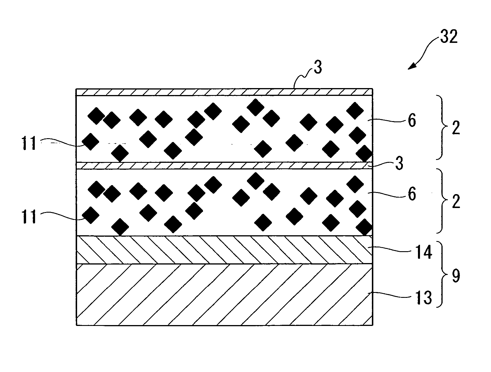
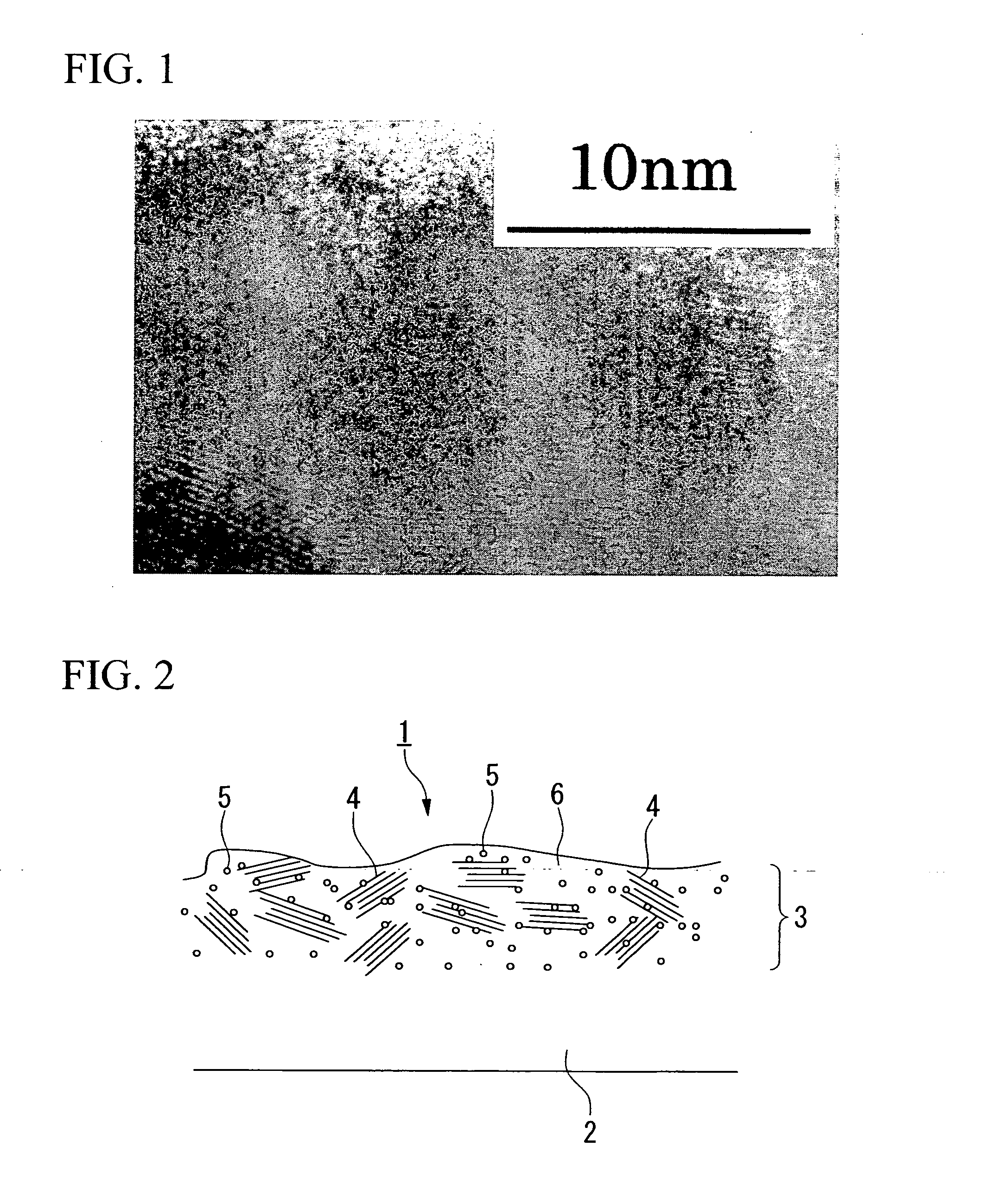
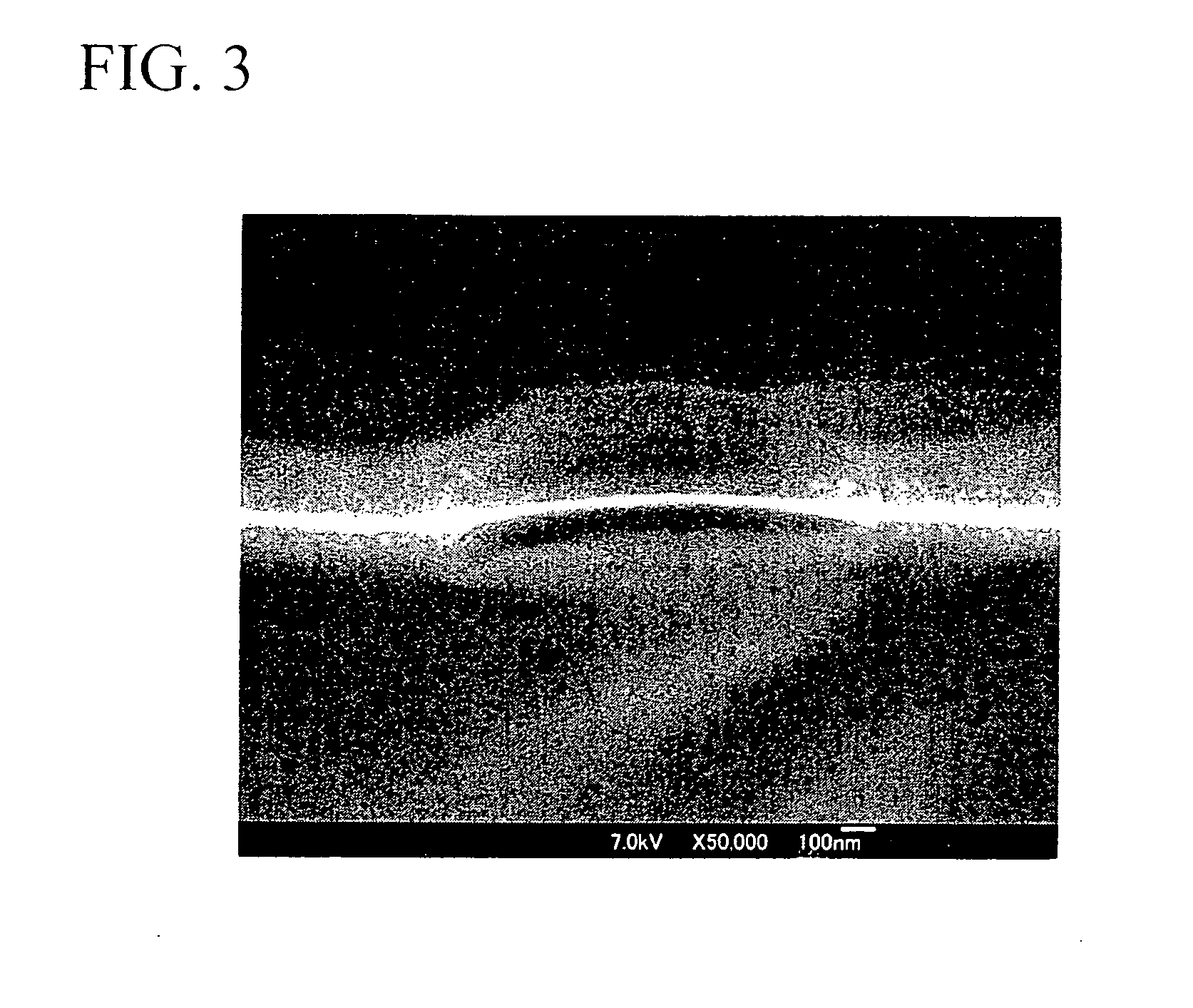
[0256] A composite layer was formed by sputtering Mn—Zn-based high magnetic permeability ferrite to equivalent thickness of 3 nm by opposing target type magnetron sputtering process on a polyethylene phthalate (hereinafter referred to as PET) film used as the base material having a thickness of 12 μm, elastic modulus in shear of 3.8×10⁹ (Pa), carbon dioxide gas permeability of 1×10⁻¹¹ [cm3 (STP) cm / (cm2×s×cmHg)] and mean surface roughness of 1.8 μm. Surface resistivity of the composite layer was measured by DC 4-terminal method. The film was trimmed to a predetermined size, and ten sheets of this film were stacked one on another via polyester adhesive. The stack was consolidated by vacuum press thereby making the electromagnetic noise suppressor measuring 138 μm in total thickness. Then specific gravity and electromagnetic noise suppressing characteristic were measured. The results are shown in Table 1.

example 2

[0257] A silicone rubber having a thickness of 20 μm, elastic modulus in shear of 1×10⁷ (Pa), carbon dioxide gas permeability of 2.2×10⁻⁷ [cm3 (STP) cm / (cm2×s×cmHg)] was provided as the base material on a PET film used as the support layer having a thickness of 25 μm, and thereon composite layer was formed by sputtering Fe—Ni-based soft magnetic metal to equivalent thickness of 20 nm by the opposing target type magnetron sputtering process. Surface resistivity of the composite layer was measured by DC 4-terminal method. The film was trimmed to a predetermined size, and thereby making the electromagnetic noise suppressor measuring 45 μm in total thickness. Then specific gravity and electromagnetic noise suppressing characteristic were measured. The results are shown in Table 1.

example 3

[0258] A urethane gel having a thickness of 10 μm, elastic modulus in shear of 1.7×10⁶ (Pa), carbon dioxide gas permeability of 5.3×10⁻⁸ [cm3 (STP) cm / (cm2×s×cmHg)] was provided as the base material on a PET film used as the support layer having a thickness of 25 μm, and thereon a composite layer was formed by sputtering Fe—Si—Al-based soft magnetic metal to equivalent thickness of 15 nm by magnetron sputtering process (non-opposing target type). Surface resistivity of the composite layer was measured by DC 4-terminal method. Urethane gel was applied to the composite layer to a thickness of 2 μm, and sputtering was carried out again. This process was repeated to form three composite layers thereby to obtain the electromagnetic noise suppressor measuring 79 μm in total thickness. Then specific gravity and electromagnetic noise suppressing characteristic were measured. The results are shown in Table 1.


PUM

PropertyMeasurementUnit
thicknessaaaaaaaaaa
thicknessaaaaaaaaaa
thicknessaaaaaaaaaa

Abstract

An electromagnetic noise suppressor of the present invention includes a base material 2 containing a binding agent and a composite layer 3 formed by integrating the binding agent that is a part of the base material 2 and the magnetic material. This electromagnetic noise suppressor has high electromagnetic noise suppressing effect in the sub-microwave band, and enables it to reduce the space requirement and weight. The electromagnetic noise suppressor can be manufactured by forming the composite layer 3 on the surface of the base material 2 by physical vapor deposition of the magnetic material onto the surface of the base material 2. The article with an electromagnetic noise suppressing function of the present invention is an electronic component, a printed wiring board, a semiconductor integrated circuit or other article of which at least a part of the surface is covered by the electromagnetic noise suppressor of the present invention.

Description

TECHNICAL FIELD [0001] The present invention relates to an electromagnetic noise suppressor that suppresses electromagnetic noise, an article with an electromagnetic noise suppressing function, and a method of manufacturing the same. BACKGROUND ART [0002] In recent years, as the use of the Internet increases, electoronic apparatuses that use CPUs running at high clock frequencies in the sub-microwave band (0.3 to 10 GHz), electronic apparatuses that use high frequency bus, and telecommunication apparatuses that utilize radio waves have been increasing, such as personal computers, home appliances having information processing functions, wireless LAN, bluetooth-equipped apparatuses, optical module, mobile telephones, mobile information terminals and intelligent road traffic information system. This trend leads to a society of ubiquitous computing that requires devices of higher performance with high-speed digital information processing function and low-voltage driving. However, as suc...

Claims


Application Information

Patent Timeline
Patent Type & Authority Applications(United States)
IPC IPC(8): B32B15/00C23C14/00H01F10/08H01F41/18H05K1/02H05K3/28H05K9/00
CPCH01F10/08H01F41/18H01F2017/065H05K1/0233Y10T428/32H05K9/0083Y10T428/25Y10T428/26Y10T156/10H05K3/28Y10T428/31504
Inventor KAWAGUCHI, TOSHIYUKIFUJIKI, HIRONAOTANIGUCHI, ATSUSHIGONDA, TAKASHITAHARA, KAZUTOKI
Owner SHIN-ETSU POLYMER CO LTD
Why Eureka
Try Eureka