

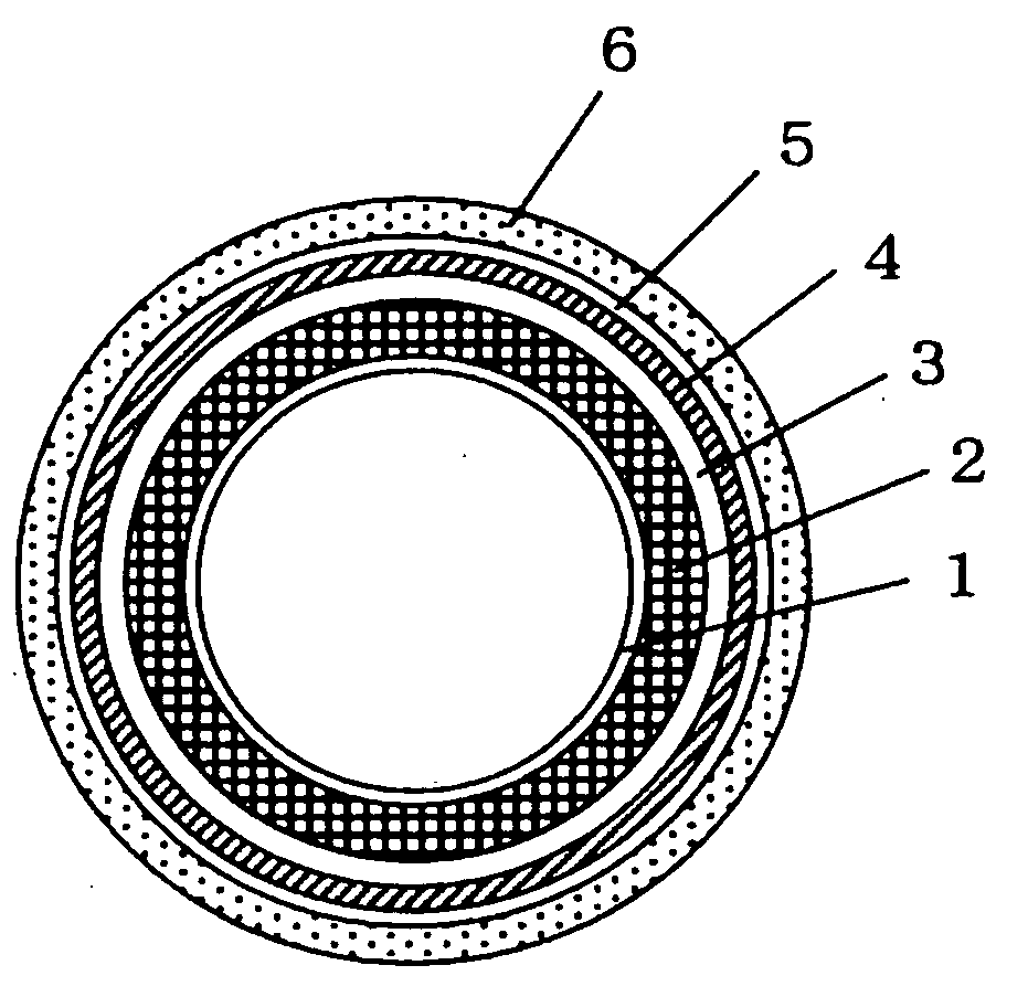
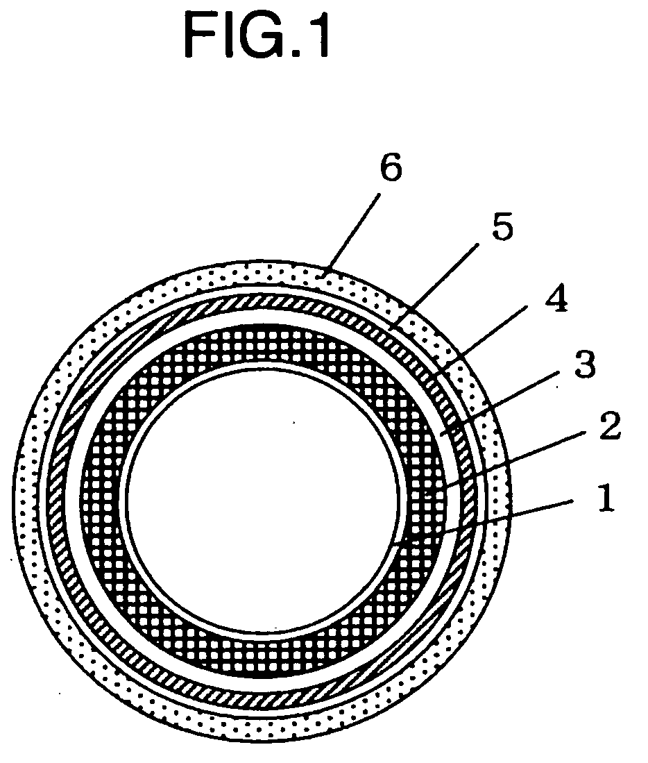
Hollow Cylindrical Printing Element
a cylindrical printing element and cylindrical printing technology, applied in the field of cylindrical printing original plates, can solve the problems of large time consumption, large time consumption, and large scattering of glass fibers used for reinforcing, and achieve the effect of simple and fast formation, good plate thickness accuracy and dimensional accuracy
- Summary
- Abstract
- Description
- Claims
- Application Information
AI Technical Summary
Benefits of technology
Problems solved by technology
Method used
Image

Examples
production example 1
[0139]A 1-liter separable flask equipped with a thermometer, a stirring device and a reflux system was charged with 447.24 g of a polycarbonate diol manufactured by Asahi Kasei Corporation (PCDL L4672™; number average molecular weight of 1,990; OH number 56.4) and 30.83 g of tolylene diisocyanate. The resultant mixture was reacted for about 3 hours under heating at 80° C., and then charged with 14.83 g of 2-methacryloyloxy isocyanate. This mixture was further made to react for about 3 hours, to thereby produce a resin (d1) having a methacrylic group on a terminal (an average of about 2 polymerizable unsaturated groups per molecule) and whose number average molecular weight was about 10,000. This resin was like a starch syrup at 20° C., and would flow if applied with an external force, but would not return to its original form when the external force was removed.
production example 2
[0140]A 1-liter separable flask equipped with a thermometer, a stirring device and a reflux system was charged with 447.24 g of a polycarbonate diol manufactured by Asahi Kasei Corporation (PCDL L4672™; number average molecular weight of 1,990; OH number 56.4) and 30.83 g of tolylene diisocyanate. The resultant mixture was reacted for about 3 hours under heating at 80° C., and then charged with 7.42 g of 2-methacryloyloxy isocyanate. This mixture was further made to react for about 3 hours, to thereby produce a resin (d2) having a methacrylic group on a terminal (an average of about 1 polymerizable unsaturated group per molecule) and whose number average molecular weight was about 10,000. This resin was like a starch syrup at 20° C., and would flow if applied with an external force, but would not return to its original form when the external force was removed.
production example 3
[0141]A 1-liter separable flask equipped with a thermometer, a stirring device and a reflux system was charged with 449.33 g of a polycarbonate diol manufactured by Asahi Kasei Corporation (PCDL L4672™; number average molecular weight of 1,990; OH number 56.4) and 12.53 g of tolylene diisocyanate. The resultant mixture was reacted for about 3 hours under heating at 80° C., and then charged with 47.77 g of 2-methacryloyloxy isocyanate. This mixture was further made to react for about 3 hours, to thereby produce a resin (d3) having a methacryl group on a terminal (an average of about 2 polymerizable unsaturated groups per molecule) and whose number average molecular weight was about 3,000. This resin was like a starch syrup at 20° C., and would flow if applied with an external force, but would not return to its original form when the external force was removed.
(Formation of a Hollow Cylindrical Core Material)
[0142]A photosensitive resin compound (XI) which was a liquid at 20° C. was o...
PUM
| Property | Measurement | Unit |
|---|---|---|
| Temperature | aaaaa | aaaaa |
| Length | aaaaa | aaaaa |
| Length | aaaaa | aaaaa |
Abstract
Description
Claims
Application Information