[0021]In one embodiment of the invention, the
alkaline fuel cell is fed at the cell anode with the
fuel vapor originated from a highly concentrated hydrocarbon
aqueous solution or neat hydrocarbon fuels from the fuel
cartridge inserted inside the fuel
cell system. The highly concentrated hydrocarbon
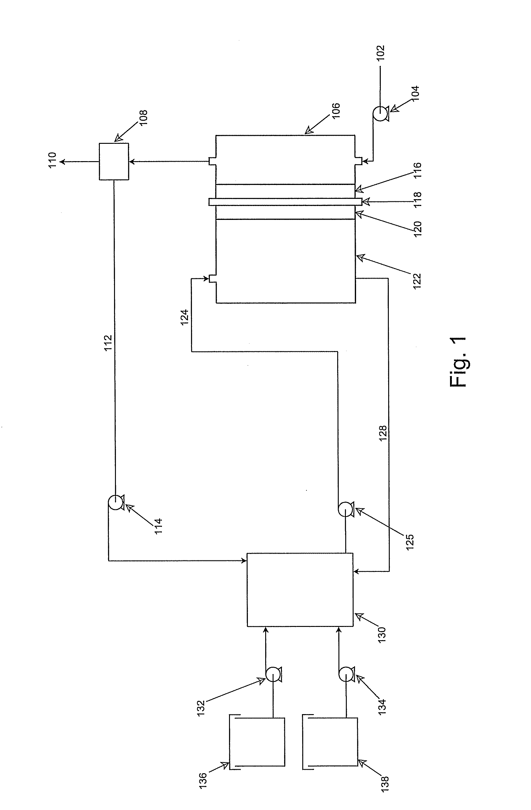
aqueous solution or neat hydrocarbon fuels can also be directly injected into a reservoir placed inside the fuel cell system. The concentrated hydrocarbon
aqueous solution or neat hydrocarbon fuel from the fuel
cartridge or reservoir contains no
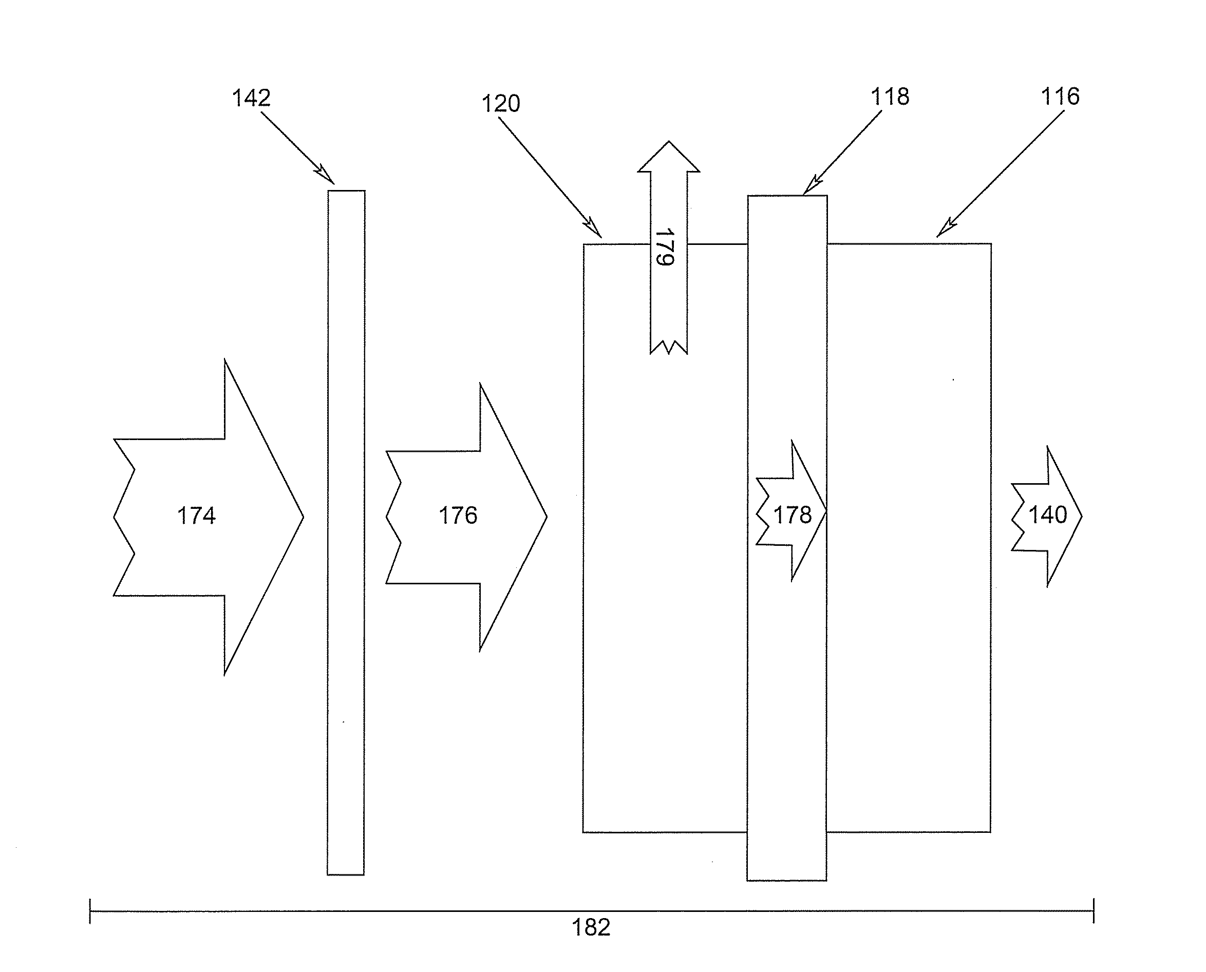
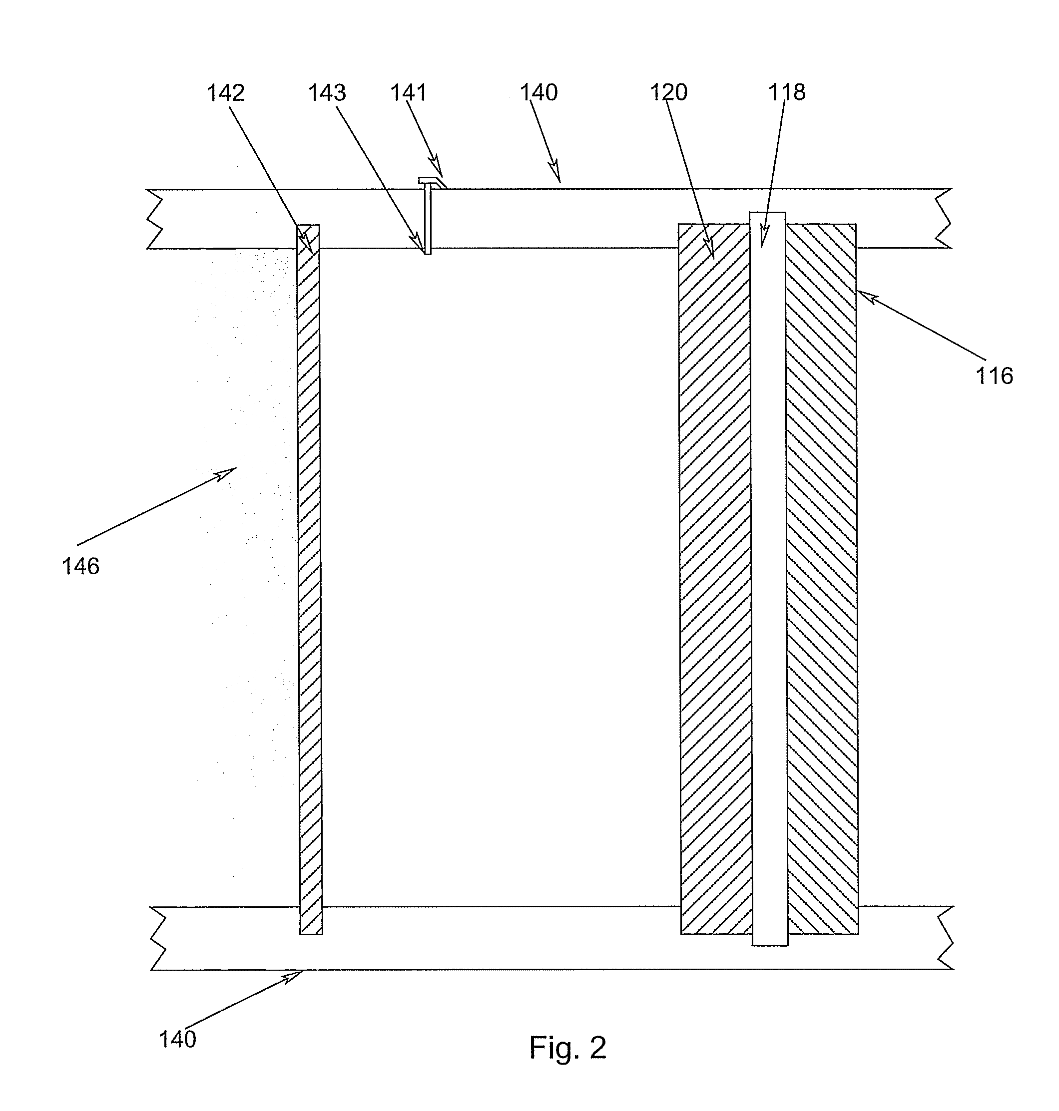
electrolyte, and is separated from its vapor with an evaporative membrane or other micro-porous materials, which is disposed inside the cell anode compartment between the fuel reservoir and fuel cell anode
electrode. Fuel in liquid form is presented at one side of the evaporative membrane while fuel in vapor form at the other side of the evaporative membrane. The fuel vapor has a direct access to the fuel cell
anode catalyst layer. The anodic
electrode reaction produces CO2, which is released through openings located between the fuel
evaporation membrane and fuel cell anode, or through the
membrane electrode assembly at the cell cathode. Part of the water produced from the anodic
electrode reaction of such an
alkaline fuel cell is forced to flow through the
polymer electrolyte membrane from cell anode to cell cathode by a
positive pressure intentionally built-up with CO2 produced at the anode side of the MEA. In addition,
water transport from the cell anode to cell cathode is further facilitated by a
hydrodynamic pressure intentionally designed with the MEA structure. In such a MEA, the
anode catalyst layer is made to be highly hydrophobic and the
cathode catalyst layer to be highly hydrophilic. As the result, a
hydrodynamic pressure arises from the hydrophobicity difference between a highly hydrophobic
anode catalyst layer and a highly hydrophilic
cathode catalyst layer, and water is pushed out of the anode catalyst layer and pulled into the
cathode catalyst layer. With these water management design, the water needs at the cell cathode for the cathodic electrode reaction and OH— conduction of the
polymer electrolyte can be self-sustained by the
water production from cell electrode reactions. This is unlike a direct hydrocarbon fuel cell fed with a
liquid fuel solution directly to the cell anode, where an external mechanical pumping system must be used for recovering water from exhaust and returning the recovered water to the system. Additional benefits derived from the vapor fed direct hydrocarbon fuel cell include
high energy density by removing the need to carry water, insensitivity to its orientation along gravity, withstanding
frozen temperature, simple and reliable operation, low potential hazardous
exposure of the corrosive electrolyte to
end user, and low cost in
mass production. The anode catalyst layer and cathode catalyst layer with specially designed hydrophobicity, a membrane or microporous medium that separate the
liquid fuel and its fuel vapor, and a suitable OH—
conductive polymer electrolyte membrane or
porous medium soaked with an alkaline
hydroxide solution are the key components for the vapor fed direct hydrocarbon fuel cell to work well.
[0028]In accordance with another aspect of the embodiments of the invention, optimal
water content within the fuel cell electrodes is be further more maintained by adjusting fuel cell temperature through fuel cell operating
power output. The fuel cell
power output can be adjusted by the fuel feed rate, and with a given fuel feed rate by the fuel cell
operating voltage. With a higher fuel cell operating power, a higher rate of
waste heat is generated, thus raises the cell temperature higher. The higher difference between cell temperature above the ambient temperature increases water removal from the cell cathode by
evaporation.

