Negative thermal expansion materials including method of preparation and uses therefor

Inactive Publication Date: 2001-02-13
CORNING INC
View PDF6 Cites 85 Cited by
  • Summary
  • Abstract
  • Description
  • Claims
  • Application Information

AI Technical Summary

Benefits of technology

The present invention involves the discovery of an alternative to prevent microcracking. Applicant has discovered that the combination of a material having a strongly negative CTE, for example, a first material such as ZrW.sub.2 O.sub.8 having a room temperature CTE more negative than -50.times.10.sup.-7.degree. C..sup.-1, with a second phase whose CTE is also negative, but not as strongly negative as that of the first material, results in lower stresses from the CTE mismatch between the phases. Thus, the present invention provides a body that avoids microcracking for grain sizes less than about 15 microns, preferably less than about 10 microns. In an additional alternative embodiment, the grain sizes are greater than 1 micron.
Applicant has recently measured the room temperature CTE of the compound Zr.sub.2 P.sub.2 WO.sub.12 to be about -40.times.10.sup.-7.degree. C..sup.-1. Applicant has discovered that because the CTE of this compound is not extremely different from that of ZrW.sub.2 O.sub.8, a ceramic body containing both phases can exhibit a CTE of intermediate value without undergoing microcracking, provided that the grain size of the two components is less than about 10 microns. This restriction on grain size can easily be met for an appropriate choice of starting materials and sintering conditions.
According to an exemplary embodiment of the present invention, powders of ZrW.sub.2 O.sub.8 and Zr.sub.2 P.sub.2 WO.sub.12, or precursors that form ZrW.sub.2 O.sub.8 and Zr.sub.2 P.sub.2 WO.sub.12 by reaction upon firing, or their hafnium analogues or mixtures thereof, are mixed together and formed into the desired shape by ceramic processes known in the art, e.g., dry pressing, injection molding, extrusion, slip casting, etc. Mixing may be performed on the dry powders, or the powders may be mixed with a liquid and may optionally be further reduced in particle size by ball milling, attrition milling, vibratory milling, etc. An organic binder may be added to the powders to increase handling strength in the green (pre-fired) state. Opt

Problems solved by technology

On the other hand, materials having negative mean lattice expansions that do not require microcracking for negative bulk ceramic CTEs are even more limited, and include certain synthetic alkali-free zeolites having low aluminum contents, ZrW.sub.2 O.sub.8, HfW.sub.2 O.sub.8, ZrV.sub.2-x P.sub.x O.sub.7 (above about 100.degree. C.
Of the compounds that have negative mean lattice expansions, zeolite expansions from 25 to 100.degree. C. are in the range -20.times.10.sup.-7.degree. C..sup.-1 to -40.times.10.sup.-7.degree. C..sup.-1, but have the disadvantages of being dependent upon the amount of adsorbed water in the zeolite, and their CTE curves can exhibit considerable hysteresis.
Such high porosity bodies generally are not useful for industrial applications.
Large relative differences in the thermal expansion coefficients of ZrW.sub.2 O.sub.8 and the positive CTE materials can cause microcracking in the composite material upon heating and cooling o

Method used


Image

  • Negative thermal expansion materials including method of preparation and uses therefor
  • Negative thermal expansion materials including method of preparation and uses therefor
  • Negative thermal expansion materials including method of preparation and uses therefor

Examples


examples 1-18

were prepared by mixing together powders of zirconium oxide, tungsten oxide, and acid zirconium phosphate, Zr(HPO.sub.4).sub.2.0.93H.sub.2 O, in the proportions required to yield the compound Zr.sub.2 P.sub.2 WO.sub.12 after firing. Mixtures for Examples 2-18 also contained 1 weight percent addition of a metal oxide, or metal oxide forming source. Powders were mixed with a sufficient amount of isopropanol to form a slurry, and the slurry was milled in a vibratory mill for approximately sixteen hours using zirconium oxide milling media. The slurry was subsequently dried in a dish at about 85.degree. C., repulverized, and the powder pressed into 1.2 cm diameter, 0.4 cm thick pills, or 7.6 cm.times.1.3 cm.times.0.4 cm bars in a steel mold at a pressure of about 70 Mpa (10,000 pounds / inch.sup.2). The pills and bars were placed on coarse zirconium oxide sand in covered aluminum oxide setter boxes inside of an electrically heated furnace. Temperature of the furnace was raised at a rate of...

example 1

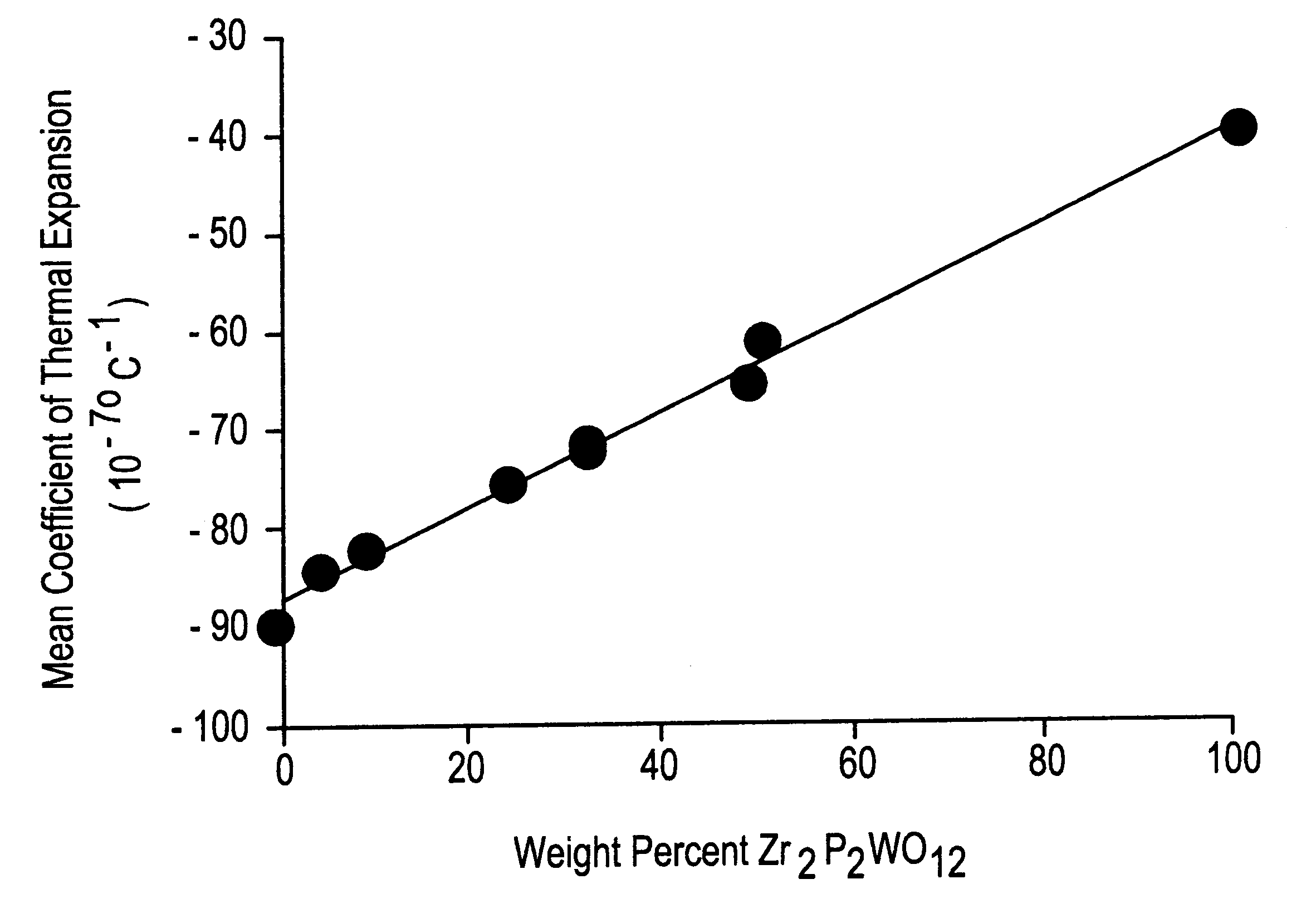
shows that, in the absence of a sintering additive, the Zr.sub.2 P.sub.2 WO.sub.12 ceramic was poorly densified, containing about 32 percent porosity. The mean coefficient of thermal expansion (CTE) from 25 to 50.degree. C. was -32.times.10.sup.-7.degree. C..sup.-1, and from 25 to 500.degree. C. was -30.times.10.sup.-7.degree. C..sup.-1. This specimen consisted entirely of the desired Zr.sub.2 P.sub.2 WO.sub.12 phase.

examples 2-4

demonstrate that the addition of only 1% of the carbonates of the alkali (Group IA) metals is highly effective in promoting densification of the Zr.sub.2 P.sub.2 WO.sub.12 ceramics. Samples contain essentially no open porosity, and total porosities are reduced to approximately 1-5%. Thermal expansions remain strongly negative at room temperature. XRD showed that these ceramic bodies contain mostly Zr.sub.2 P.sub.2 WO.sub.12 with minor amounts of LiZr.sub.2 P.sub.3 O.sub.12, NaZr.sub.2 P.sub.3 O.sub.12, and KZr.sub.2 P.sub.3 O.sub.12, in samples 2-4, respectively. These secondary phases are responsible for the somewhat less negative CTE from 25 to 500.degree. C. for Examples 2 and 3.


PUM

PropertyMeasurementUnit
Fractionaaaaaaaaaa
Fractionaaaaaaaaaa
Fractionaaaaaaaaaa

Abstract

Negative thermal expansion materials, methods of preparation and uses therefor are disclosed. The materials are useful for negative thermal expansion substrates, such as those used for optical fiber gratings.

Description

The invention pertains to negative thermal expansion materials, devices made therefrom, and methods of making the materials. More particularly, the present invention concerns compositions including zirconium phosphate tungstates, which can be used to make substrates for athermalized optical fiber reflective grating devices.Negative thermal expansion (contraction with increasing temperature) is an unusual and potentially useful property for a solid material, and very few crystalline materials possess strongly negative expansions over an extended temperature range. Materials that exhibit a negative expansion due to extensive microcracking, by virtue of a negative coefficient of thermal expansion ("CTE") along at least one crystallographic axis and a substantially different CTE along at least one other axis, include some lithium aluminosilicates, "NZPs" (compounds with crystal structures similar to that of NaZr.sub.2 P.sub.3 O.sub.12), and Ta.sub.2 O.sub.5 --WO.sub.3 compounds. On the ...

Claims


Application Information

Patent Timeline
IPC IPC(8): C04B35/495C04B35/01G02B6/12C04B35/00C04B35/48G02B6/00G02B6/02
CPCC04B35/01C04B35/495G02B6/0218G02B6/12
Inventor MERKEL, GREGORY A.
Owner CORNING INC
Why Eureka
Try Eureka