
Artificial pulmonary capillary

a technology of pulmonary capillaries and pulmonary veins, which is applied in the field of photolysis cells, can solve the problems of small construction of artificial pulmonary capillaries, sometimes almost microscopic, etc., and achieve the effects of small construction size, low cost and controllable commercial value of the technology

Inactive Publication Date: 2009-03-03
BATTELLE MEMORIAL INST
View PDF33 Cites 8 Cited by
  • Summary
  • Abstract
  • Description
  • Claims
  • Application Information

AI Technical Summary

Benefits of technology

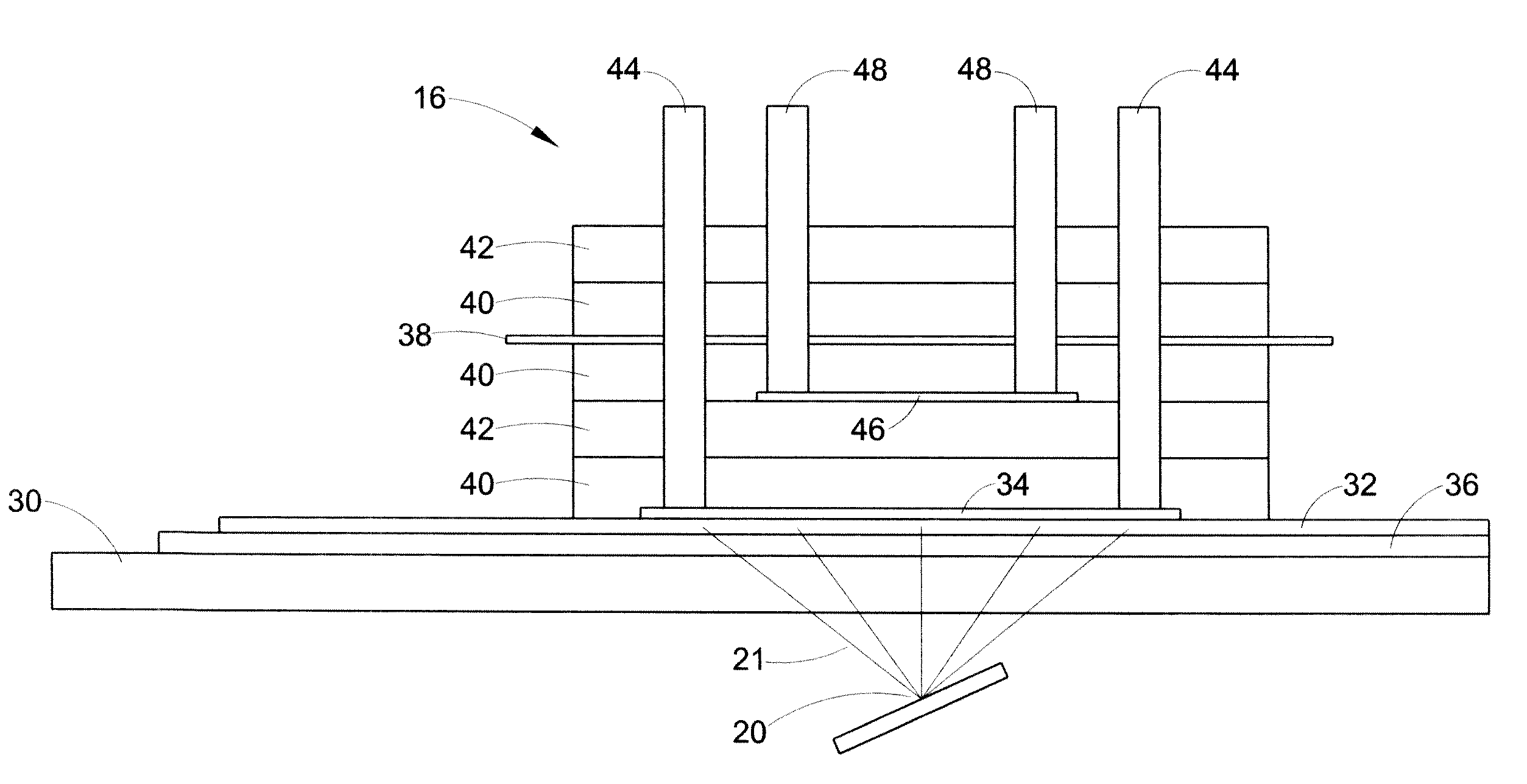
[0104]FIG. 3 shows a flow-through embodiment of the photolytic cell 16. In the flow-through cell embodiment, the following main components of the photolytic cell 16 are assembled, i.e. a conductive coating of vacuum deposited Ti metal 36, a coating of adherent TiO2 (anatase) 32, an optional MnO2 particulate layer 34, and then tested using a bicarbonate solution. A UV laser light 20 was shown on the transparent glass or quartz substrate 30 so to initiate the reactions. As discussed below, this cell was utilized to collect pH and data as a function of laser U.V. irradiation demonstrating the effectiveness of the invention.
[0105]In this regard, the photolytic cell 16 of FIG. 3 includes a transparent window 30 or wave guide for the entry of light energy in the form of photons 21 from a light source 20 such as an ultraviolet laser light. On one side of the glass slide is an anode conductor layer 36, such as titanium (Ti) metal film. Attached to the anode conductor layer 36, is a layer of a light activated catalyst 32 such as anatase (TiO2). An optional catalyst layer 34, such as manganese dioxide, is adjacent to the light activated catalyst layer 32. The photolytic cell 16 includes one or more layers of silicone gaskets or spacers 40 and an acrylic housing 42. A pair of anolytes 44 (in / out) are connected to the light activated catalyst layer 32 or optional catalyst layer 34 and extend through the photolytic cell 16 away from the transparent window 30. The photolytic cell 16 further includes a cation exchange member 46, such as a NAFION® membrane from DuPont. A pair of catholytes 48 (in / out) are connected to the cation exchange member 46 and extend outwardly through the photolytic cell 16 generally away from the transparent window 30. The photolytic cell 16 further includes a cathode layer 38, such as Pt foil, adjacent to the cation exchange member 46. The operation and use of this embodiment of the invention is more particularly described in the Examples below.
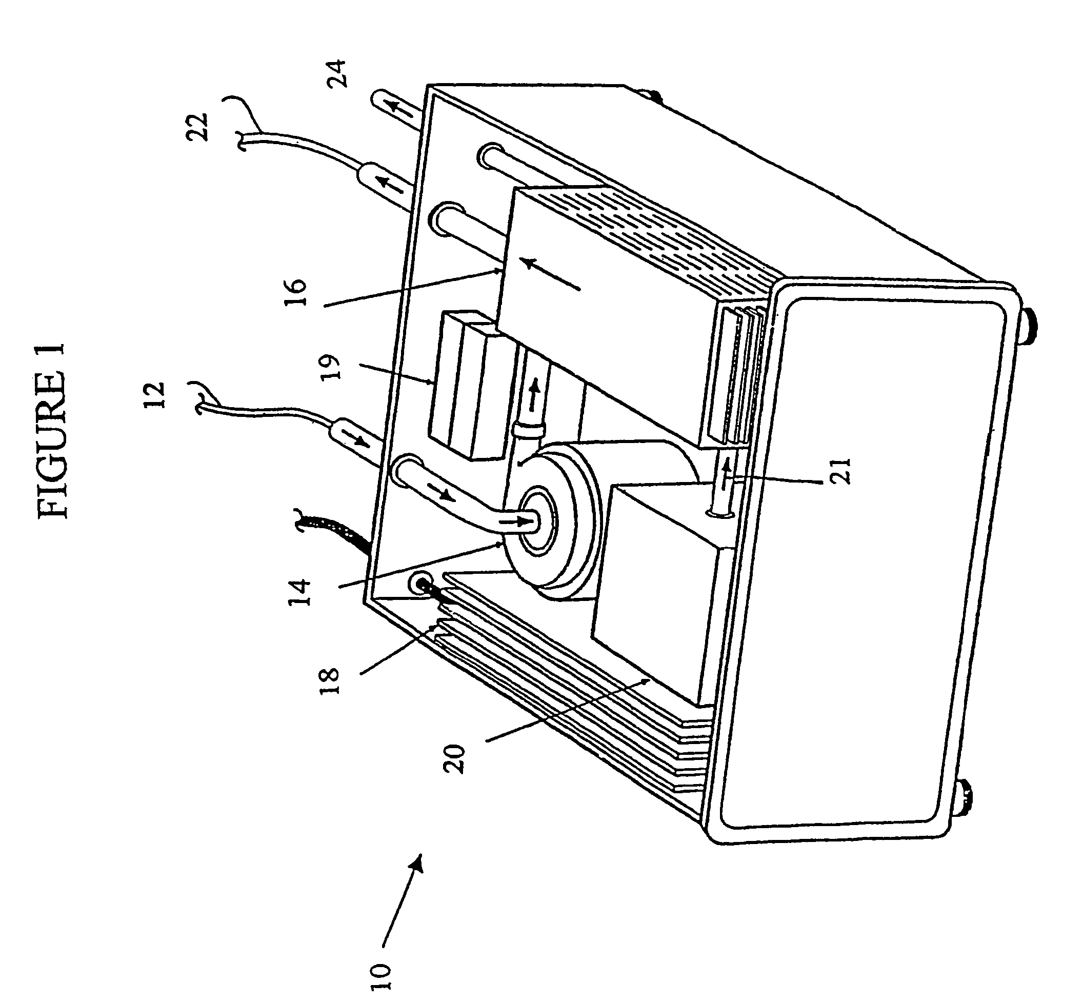
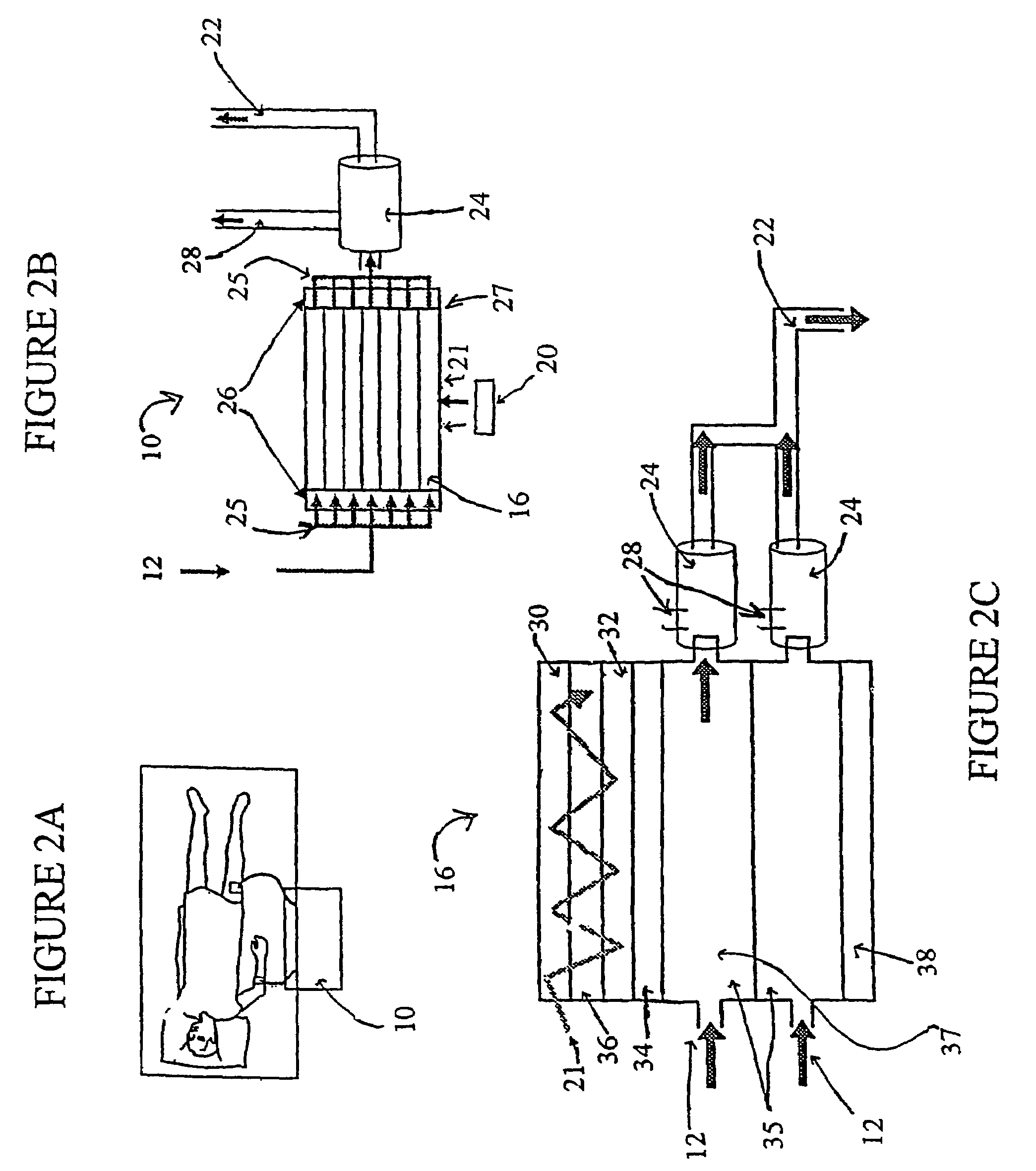
[0106]FIG. 4 is a schematic drawing showing the electrical and chemical transformations which occur in the photolytic cell 16 of the photolytic artificial lung 10. Venous blood (low in oxygen and high in carbon dioxide) from a patient enters the photolytic cell 16 through inlet 12 by way of a peristaltic pump 14. Light photons (hv) 21 generated by light source 20 enter through a transparent window 30 or waveguide and activate the light activated catalyst 32 such as 100 μm TiO2 (anatase). The light activated catalyst 32 either directly converts water to dissolved oxygen or converts water to active oxygen and hydrogen ions and an optional second catalyst 34, such as manganese dioxide (MnO2) on a porous film, converts active oxygen (e.g. H2O2) into dissolved oxygen (DO). The dissolved oxygen then binds to hemoglobin present in the blood.
[0107]The electrons released from the conversion of water to oxygen are collected in the collector electron anode 36. An electrical current formed from a battery 49 allows the electrons to flow from the anode 36 to the cathode 38, such as graphite or nickel, so that the electrons do not react with the active oxygen to cause a back reaction and the reformation of water.
[0108]The electrical current and electron flow can be regulated by a current regulator 50 or resistor 52. The electrons can react with water to form hydrogen gas, H2, and a hydroxyl ion (OH−). The hydrogen gas formed is moved to a gas sorption device, where it is stored and / or released (i.e., expired). Sodium (Na+) ions from the blood migrate across the cation exchange membrane 46 and react with hydroxyl ions to form sodium hydroxide (NaOH) in the catholyte 48. The hydrogen ions formed from the conversion of water at the light activated catalyst reacts with bicarbonate ions to form carbonic acid, which is converted by carbonic anhydrase enzyme present in the blood or added to form carbon dioxide and water. The carbon dioxide formed in the photolytic cell 16 along with the carbon dioxide released from the blood is moved to one or more gas sorption devices 24 or vented. The oxygenated blood exits the photolytic cell 16 via an outlet 22 and returns to the artery of the patient.
[0109]The various particular components and / or processes of the flow through photolytic cell embodiment of the present invention are described in more detail below:

Problems solved by technology

However, the artificial pulmonary capillary is of smaller (i.e. sometimes nearly microscopic) construction.

Method used


Image

  • Artificial pulmonary capillary
  • Artificial pulmonary capillary
  • Artificial pulmonary capillary

Examples


example 1

[0242]A prototype photolytic artificial lung was produced in order to demonstrate the ability of the device and accompanying processes to re-oxygenate synthetic blood serum (Locke's Ringer Solution), with concomitant CO2 removal and pH control, using thin film constructs. In this regard, a photolytic test flow cell (see FIG. 3) was constructed using exemplar materials for the elements of the photolytic artificial lung—a conductive coating of vacuum deposited Ti metal, a coating of adherent TiO2 (anatase), a MnO2 particulate layer, and then a bicarbonate solution. A U.V. laser light was introduced to the transparent glass or quartz substrate. This cell was used to collect pH and cell electrical current data as a function of laser U.V. irradiation. The details of the construction of such a prototype and the results produced thereby are discussed below.

[0243]In this regard, a photolytic test flow cell as shown in FIG. 3 of the photolytic artificial lung was prepared. Specifically, amon...

example 2

[0278]To demonstrate the ability of the photolytic reaction sequence to generate DO, two Hansatech batch reactors were set up, one for liquid phase (DO), and one for gas phase oxygen (PO2) detection. Both gas tight reactors were fitted with an oxygen membrane sensor and a window for illumination. These reactors were designed to allow quantitative assessments of oxygen production and quantum yields. Although, the results verify that DO can be produced photolytically from water, and that O2 can be produced from AO using a thin film catalyst.

[0279]The critical step of photolytically producing DO from H2O was illustrated in the liquid phase cell using a slurry of the anatase titania (TiO2) photon absorber and dissolved ferric ion at pH 1.9 as an electron absorber. While not intended to be used in the final device, the use of ferric ions here allows the tests to be run within the setting of the electrically isolated cell, in which the ferric ions are maintained in solution by the relativ...

example 3

[0282]A test cell was created to determine the extent to which the indicated chemical conversions occurred only during illumination, and in association with the active surface material. FIG. 3 is a diagram of the flow cell constructed with the essential elements of design, a conductive coating of vacuum deposited Ti metal, a coating of adherent TiO2 (anatase) and a MnO2 particulate layer. UV laser light was introduced to irradiate transparent glass or quartz substrate. This cell was used to collect pH, electrical current, dissolved oxygen, and gas phase CO2 data as a function of laser irradiation.

Synthesis of Photoactive Layers

[0283]The photoactive constructs consisted of a glass substrate, a conducting layer, and a photoactive layer. The glass substrates were 25 mm×9 mm in size, and 98% transmissive at the desired wavelength. The (Ti) conductive layer(s) were laid down on the glass surface using a vacuum sputter coating procedure. In order to validate the efficiency of Ti, various ...


PUM

PropertyMeasurementUnit
Nanoscale particle sizeaaaaaaaaaa
Temperatureaaaaaaaaaa

Abstract

The present invention is directed to a photolytic cell, and to a photolytic artificial lung incorporating such a cell. The photolytic artificial lung converts water to oxygen for blood absorption, regulates pH, the removes carbon dioxide, and co-produces electrical power. The photolytic artificial lung includes a photolytic cell where all of the chemical reactions occur. Additionally, the present invention relates to photolytically sensitive materials for oxygen generation. These materials are useful for gas-free artificial lung and / or pulmonary capillary fabrication. The photolytic cell disclosed herein can also be used to direct chemical reactions in organs other than the lung.

Description

[0001]The present application claims priority to U.S. patent application Ser. No. 09 / 920,385, filed on Aug. 1, 2001; U.S. Provisional Application Ser. No. 60 / 358,448, filed on Feb. 20, 2002; and U.S. Provisional Application Ser. No. 60 / 388,977, filed on Jun. 14, 2002.FIELD OF THE INVENTION[0002]The present invention is principally directed to a photolytic cell (or module) that utilizes light energy to achieve physiological gas exchange in fluids. The photolytic cell can be used to provide oxygen generation, such as in the blood stream of a patient. The present invention is also directed to a photolytic artificial lung (“PAL”) and / or an artificial pulmonary capillary incorporating such a cell. In a further embodiment, the invention relates to the use of mesoporous materials in the photolytic cell to enhance gas exchange. The invention finds particular applications in conjunction in the field of artificial organs and the medical arts.BACKGROUND OF THE INVENTION[0003]The lung is the ma...

Claims


Application Information

Patent Timeline
IPC IPC(8): A61M37/00A61M1/00C10B25/00A61M1/22A61K35/14A61L27/00A61M1/16A61M1/32A61M1/36
CPCA61M1/32A61M1/3627A61M1/3681A61M1/3687B01J21/063B01J35/004A61M1/327A61M1/3683A61M2205/8206Y10T442/176A61M60/148B01J35/39
Inventor MONZYK, BRUCE F.BURCKLE, ERIC C.
Owner BATTELLE MEMORIAL INST
Learn More