Throughout the world, considerable energy that could be delivered by hydroelectric plants, wind farms,
biomass conversion and solar collectors is wasted because of the lack of practical ways to save
kinetic energy, fuel and / or
electricity until it is needed.
This will hasten the rate of fossil depletion.
Cities suffer from smog caused by the use of fossil fuels.
Global
oil production has steadily increased to meet growing demand but the rate of oil discovery has failed to keep up with production.
After peak production, the global economy experiences inflation of every energy-intensive and
petrochemical-based product.
With increased
greenhouse gas collection of
solar energy in the
atmosphere greater work is done by the global atmospheric engine including more
evaporation of ocean waters, melting of glaciers and polar ice caps, and subsequent
extreme weather events that cause great losses of improved properties and natural resources.
Previous attempts to utilize
multifuel selections including
hydrogen,
producer gas, and higher
hydrogen-to-carbon ratio fuels such as
methane, fuel alcohols, and various other
alternative fuels along with or in place of
gasoline have variously encountered and failed to solve difficult problems albeit with expensive efforts, unreliable results, and frequently cause engine degradation or damage including:1) Greater
curb weight to increase engine
compression ratio and corresponding requirements for more expensive, stronger, and heavier pistons, connecting rods, crankshafts, bearings, flywheels, engine blocks, and support structure for acceptable power production and therefore heavier suspension springs, shock absorbers, starters, batteries, etc., etc.2) Requirements for more expensive valves, hardened valve seats and
machine shop installation to prevent valve wear and seat recession.3) Requirements to
supercharge to recover power losses and drivability due to reduced fuel energy per volume and to overcome compromised volumetric and thermal efficiencies.4) Multistage gaseous fuel pressure regulation with extremely fine
filtration and very little tolerance for
fuel quality variations including
vapor pressure,
octane and cetane ratings.5) Engine
coolant heat exchangers for prevention of gaseous fuel
pressure regulator freeze ups.6) Special
fuel storage tanks for low
energy density fuels.7) Special
fuel storage systems for fuels that change phase.7) Expensive and bulky solenoid operated tank shutoff valve (TSOV) and pressure
relief valve (PRD) systems.8) Remarkably larger flow metering systems.9) After dribble delivery of fuel at wasteful times and at times that produce back-torque.10) After dribble delivery of fuel at harmful times such as the exhaust
stroke to cause engine damage.11) Engine degradation or failure due to pre-
detonation and
combustion knock.12) Engine hesitation or damage due to failures to closely control fuel
viscosity,
vapor pressure,
octane rating, and burn velocity,13) Engine degradation or failure due to fuel washing,
vaporization and burn-off of lubricative films on cylinder walls and ring or rotor seals.14) Failure to prevent oxides of
nitrogen formation during
combustion.15) Failure to prevent formation of
particulates due to incomplete combustion.16) Failure to prevent
pollution due to
aerosol formation of lubricants in upper cylinder areas.17) Failure to prevent overheating of pistons, friction increases, and degradation.18) Failure to overcome damaging backfiring in intake manifold and
air cleaner.19) Failure to overcome damaging combustion and / or explosions in the exhaust
system.20) Failure to overcome overheating of exhaust
system components.21) Failure to overcome
fuel vapor lock and resulting engine hesitation or failure.
This dedicated tank approach for each fuel selection takes up considerable space, adds weight, requires additional spring and
shock absorber capacity, changes the center of gravity and center of thrust, and is very expensive.
Power loss sustained by each conventional approach varies because of the large percentage of intake
air volume that the expanding gaseous fuel molecules occupy.
Arranging for such large volumes of
gaseous hydrogen or
methane to flow through the vacuum of the intake manifold, through the intake valve(s) and into the vacuum of a cylinder on intake cycle and to do so along with enough air to support complete combustion to release the heat needed to match
gasoline performance is a monumental challenge that has not been adequately met.
Some degree of power restoration may be available by resorting to expensive, heavier, more complicated, and less reliable components for much higher compression ratios and / or by supercharging the intake system.
However, these approaches cause shortened engine life and much higher original and / or maintenance costs unless the basic engine design provides adequate structural sections for stiffness and strength.
Engines designed for
gasoline operation are notoriously inefficient.
Protective films of
lubricant are burned or evaporated causing pollutive emissions and the cylinder and
piston rings suffer wear due to lack of
lubrication.
Utilization of hydrogen or methane as homogeneous charge fuels in place of gasoline is presents an expensive challenge to provide sufficient
fuel storage to accommodate the substantial energy waste that is typical to gasoline engines.
Substitution of such cleaner burning and potentially more plentiful gaseous fuels in place of
diesel fuel is even more difficult.
Additional difficulties arise because gaseous fuels such as hydrogen,
producer gas, methane,
propane,
butane, and fuel alcohols such as
ethanol or
methanol lack the proper cetane ratings and do not ignite in rapidly
compressed air as required for efficient diesel-engine operation.
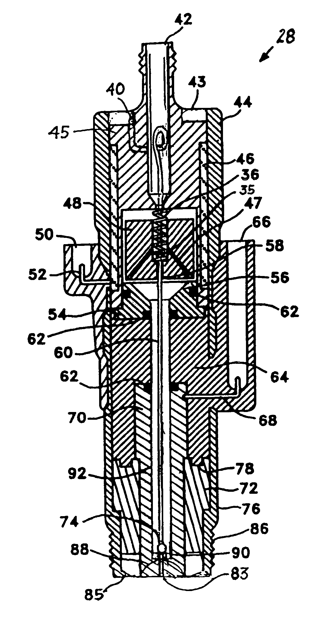
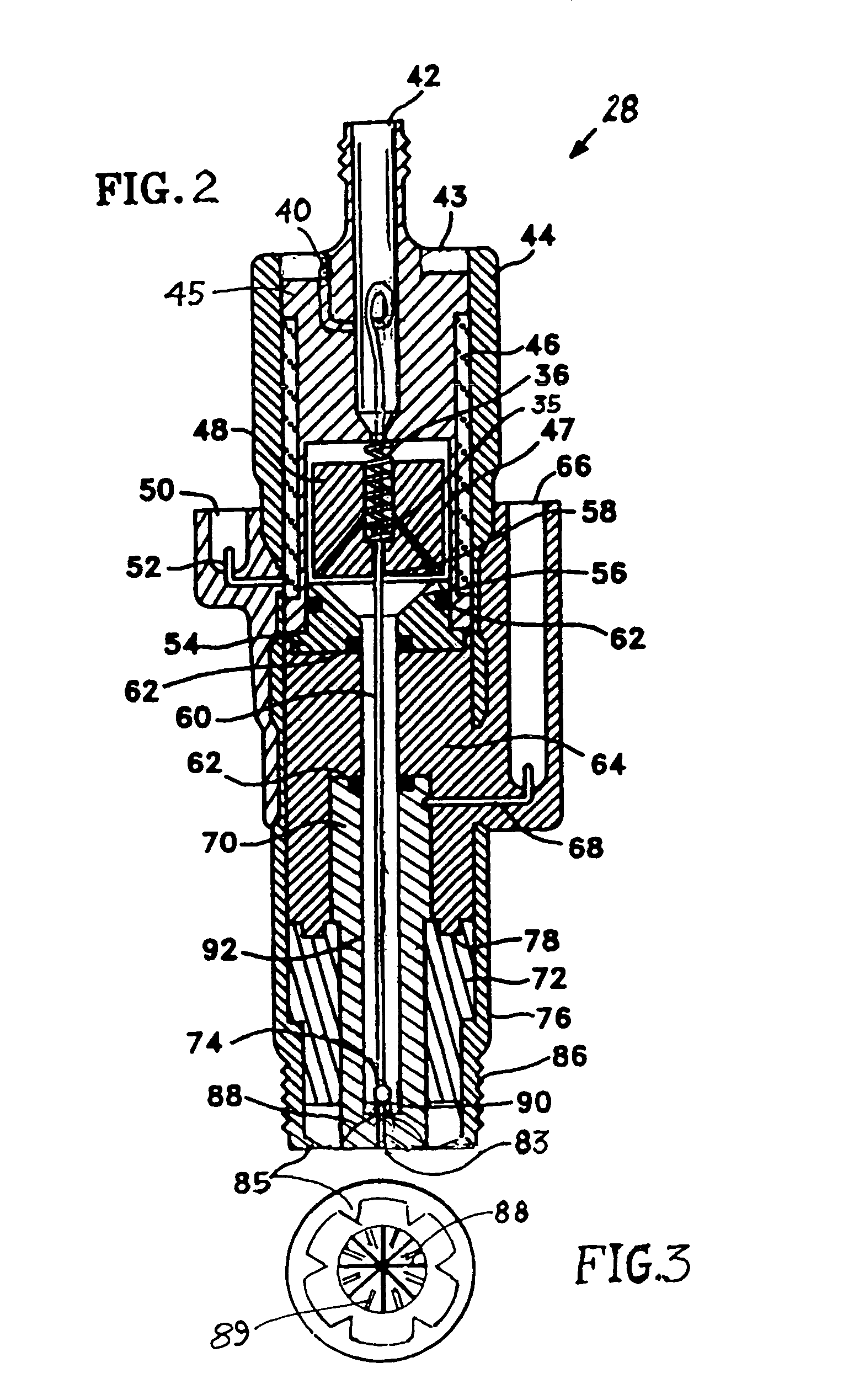
This leaves very little room in the head area for a direct cylinder fuel
injector or for a
spark plug.
Operation of higher speed valves by overhead camshafts further complicates and reduces the space available for direct cylinder fuel injectors and spark plugs.
The problem of minimal available area for spark plugs or
diesel fuel injectors is exacerbated by larger heat loads in the head due to the greater heat
gain from three to six valves that transfer heat from the
combustion chamber to the head and related components.
However this desire encounters the extremely difficult problems of providing dependable metering of such widely variant fuel densities, vapor pressures, and viscosities and to then assure subsequent precision timing of ignition.
If fuel is delivered by a separate fuel
injector to each
combustion chamber in an effort to produce a stratified charge, elaborate provisions such as
momentum swirling or ricocheting or rebounding the fuel from
combustion chamber surfaces into the
spark gap must be arranged but these approaches always cause compromising
heat losses to combustion chamber surfaces as the stratified charge concept is sacrificed.
If fuel is controlled by a metering valve at some distance from the combustion chamber, “after dribble” of fuel at wasteful or damaging times including times that produce torque opposing the intended torque will occur.
Either approach inevitably causes much of the fuel to “wash” or impinge upon cooled cylinder walls in order for some small amount of fuel to be delivered in a spark-ignitable air-fuel mixture in the
spark gap at the precise time of desired ignition.
Efforts to produce swirl of air entering the combustion chamber and to place lower density fuel within the swirling air suffer two harmful characteristics.
The inducement of swirl causes impedance to the flow of air into the combustion chamber and thus reduces the amount of air that enters the combustion chamber to cause reduced
volumetric efficiency.
After ignition, products of combustion are rapidly carried by the swirl
momentum to the combustion chamber surfaces and adverse heat loss is accelerated.
Past attempts to provide internal combustion engines with
multifuel capabilities such as the ability to change between fuel selections such as gasoline,
natural gas,
propane, fuel alcohols,
producer gas and hydrogen have proven to be extremely complicated and highly compromising.
Past approaches induced the compromise of detuning all fuels and cancel optimization techniques for specific fuel characteristics.
Such attempts have proven to be prone to malfunction and require very expensive components and controls.
These difficulties are exacerbated by the vastly differing
specific energy values of such fuels, wide range of vapor pressures and viscosities and other
physical property differences between gaseous fuels and liquid fuels.
Additional problems are encountered between cryogenic liquid or
slush and compressed-gas fuel storage of the same fuel substance.
Cryogenic methane encounters similar problems of
ice formation and damage.
These super cold fluids also cause ordinary metering orifices, particularly small orifices, to malfunction and clog.
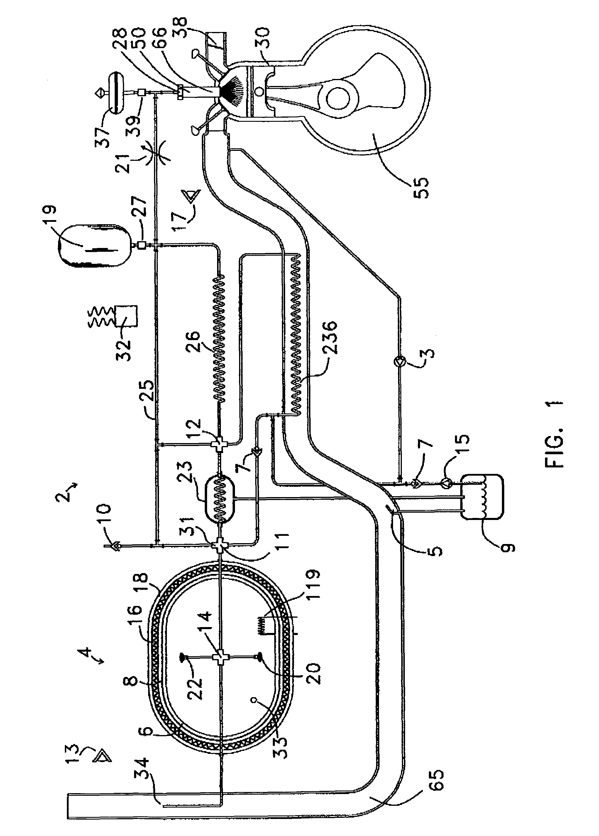
The very difficult problem that remains and must be solved is how can a vehicle be refueled quickly with dense
liquid fuel at a cryogenic (hydrogen or methane) or ambient temperature (propane or
butane) and at idle or low power levels use vapors of such fuels and at high power levels use liquid delivery of such fuels in order to meet energy production requirements?
But this goal has not been satisfactorily achieved and as a result the vast majority of motor vehicles remain dedicated to petrol even though the costs of methane and many forms of renewable hydrogen are far less than gasoline.
Similarly it has long been a goal to interchangeably use methane, hydrogen or mixtures of methane and hydrogen as cryogenic liquids and / or compressed gases in place of diesel fuel in compression-ignited engines but this goal has proven even more elusive and most diesel engines remain dedicated to pollutive and more expensive diesel fuel.

