System for electrosurgical tissue treatment in the presence of electrically conductive fluid

a tissue treatment and electrically conductive fluid technology, applied in the field of electrosurgical tissue treatment in the presence of electrically conductive fluid, can solve the problems of tissue desiccation or destruction at the contact point of the patient's tissue, cell destruction, tissue damage or destruction, etc., and achieve the effect of reducing the amount of conductive fluid and reducing the temperature of conductive fluid

Inactive Publication Date: 2010-03-16
ARTHROCARE
View PDF330 Cites 336 Cited by
  • Summary
  • Abstract
  • Description
  • Claims
  • Application Information

AI Technical Summary

Benefits of technology

[0023]In a specific configuration, the electrosurgical instrument includes an insulating member around the active electrode(s) that forms a plasma chamber adjacent to the active electrode(s). The insulating member preferably comprises an inorganic material, such as ceramic or glass, and it may comprise a transparent material that allows the physician to view the plasma formed therein. In some embodiments, the return electrode(s) are positioned exterior to the plasma chamber, proximally spaced on the instrument as described above. In other embodiments, the return elect

Problems solved by technology

These traditional electrosurgical techniques for treatment have typically relied on thermal methods to rapidly heat and vaporize liquid within tissue and to cause cellular destruction.
This current, however, may inadvertently flow along localized pathways in the body having less impedance than the defined electrical path.
This situation will substantially increase the current flowing through these paths, possibly causing damage to or destroying tissue along and surrounding this pathway.
One drawback with this configuration, however, is that the return electrode may cause tissue desiccation or destruction at its contact point with the patient's tissue.
Another limitation of conventional bipolar and monopolar electrosurgery devices is that they are not suitable for the precise removal (i.e., ablation) or tissue.
At the point of contact of the electric arcs with tissue, rapid tissue heating occurs due to high current density between the electrode and tissue.
The tissue is parted along the pathway of evaporated cellular fluid, inducing undesirable collateral tissue damage in regions surrounding the target tissue site.
The use of electrosurgical procedures (both monopolar and bipolar) in electrically conductive environments can be further problematic.
However, the presence of saline, which is a highly conductive electrolyte, can cause shorting of the active electrode(s) in conventional monopolar and bipolar electrosurgery.
Such shorting causes unnecessary heating in the treatment env

Method used


Image

  • System for electrosurgical tissue treatment in the presence of electrically conductive fluid
  • System for electrosurgical tissue treatment in the presence of electrically conductive fluid
  • System for electrosurgical tissue treatment in the presence of electrically conductive fluid

Examples


Embodiment Construction

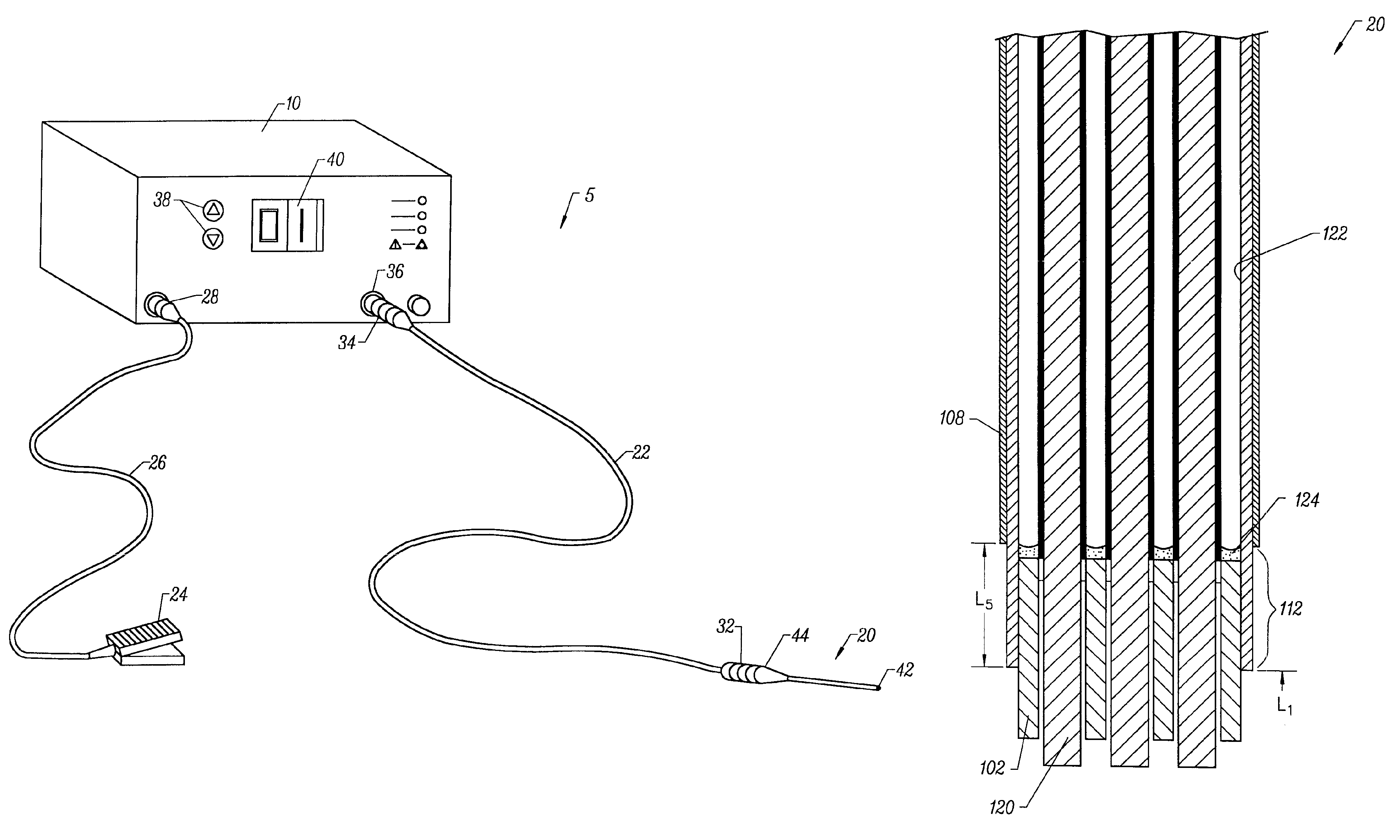
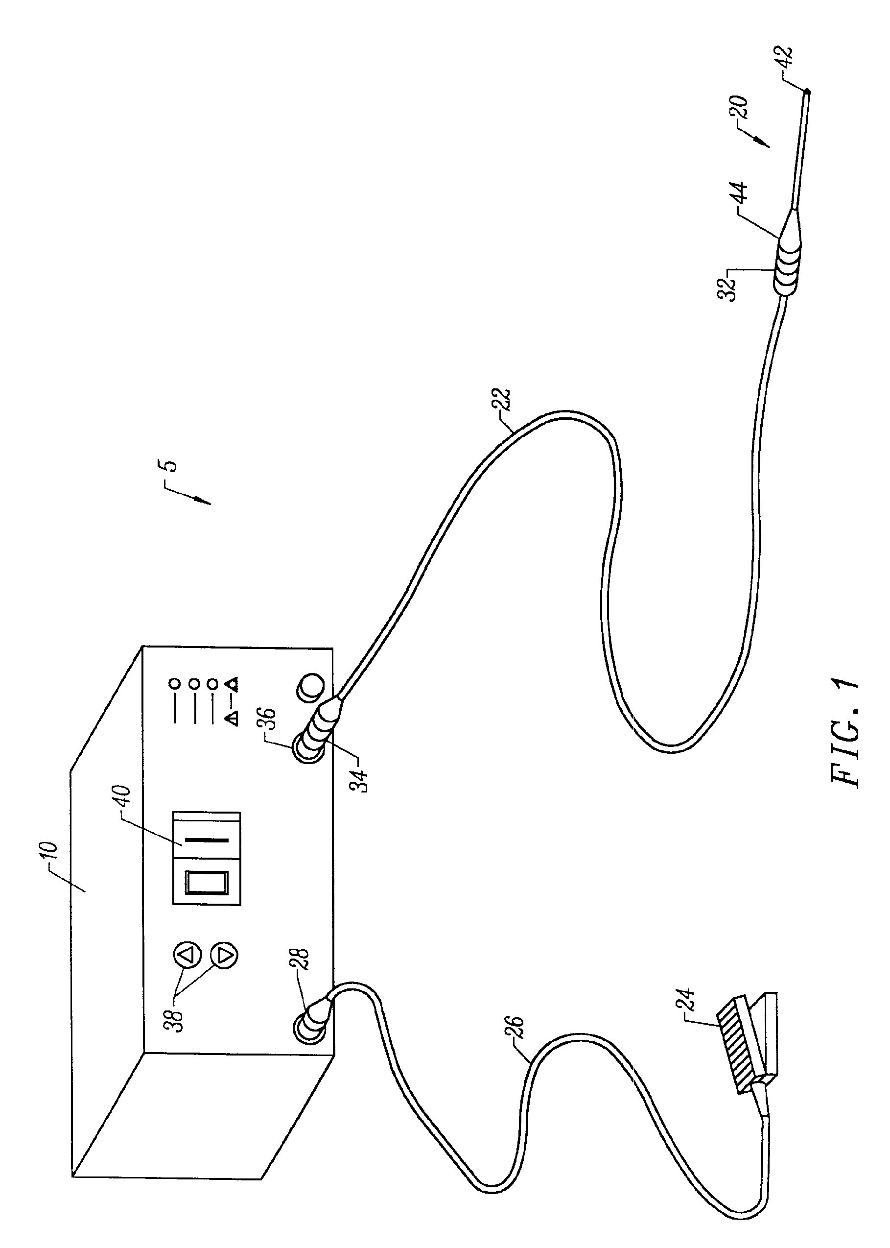
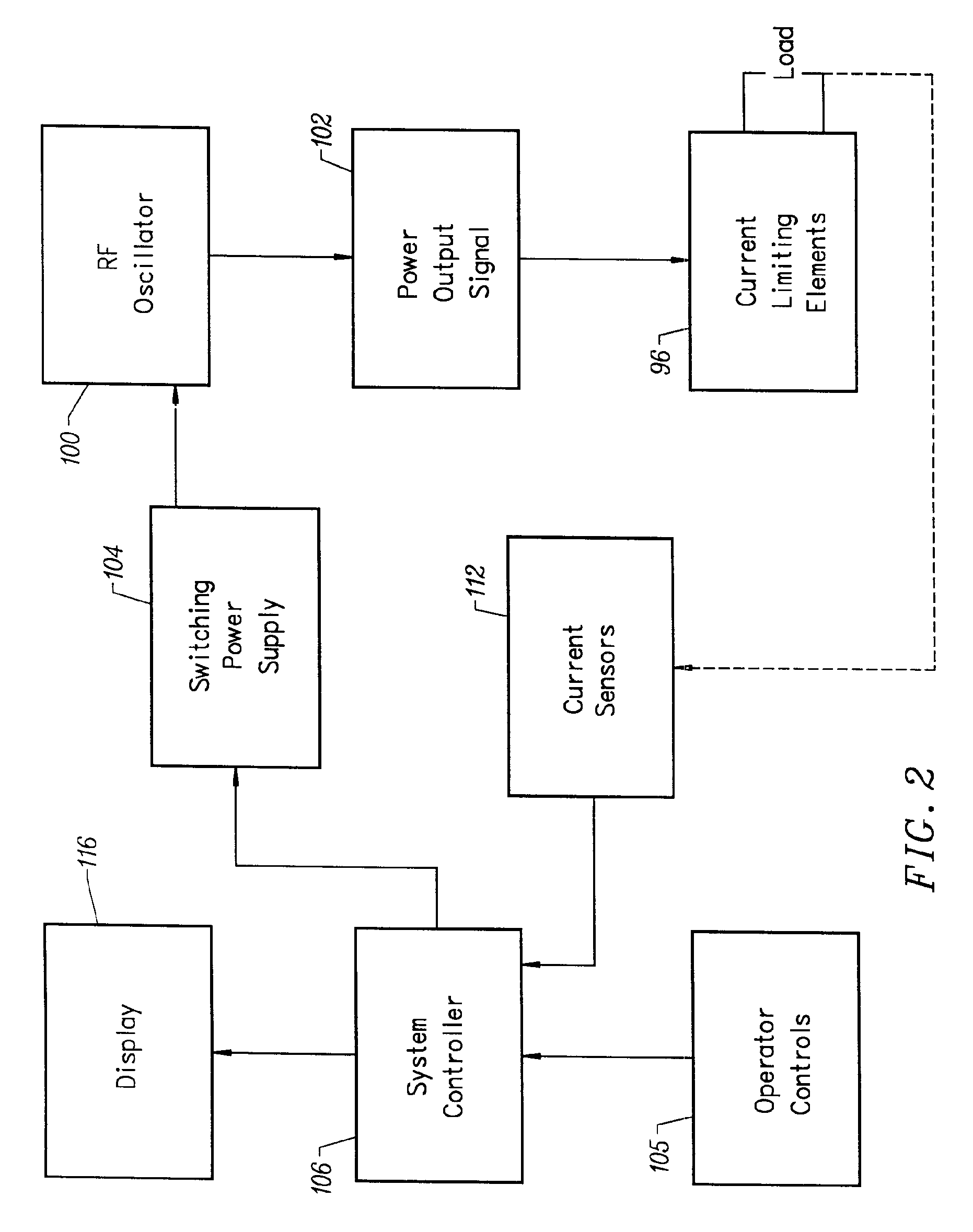
[0050]In the present invention, high frequency (RF) electrical energy is applied to one or more electrode terminals in the presence of electrically conductive fluid to remove and / or modify body tissue. The techniques of the present invention may be performed in a conventional open surgery environment or in a minimally invasive manner using cannulas or port access devices. The present invention is useful in procedures where the tissue site is flooded or submerged with an electrically conducting fluid, such as arthroscopic surgery of the knee, shoulder, ankle, hip, elbow, hand or foot. Specifically, the present invention is useful in the resection and / or ablation of the meniscus and the synovial tissue within a joint during an arthroscopic procedure. In addition, tissues which may be treated by the system and method of the present invention include, but are not limited to, prostate tissue and leiomyomas (fibroids) located within the uterus, gingival tissues and mucosal tissues located...


PUM

PropertyMeasurementUnit
Distanceaaaaaaaaaa
Electrical conductivityaaaaaaaaaa
Frequencyaaaaaaaaaa

Abstract

Systems and methods are provided for applying a high frequency voltage in the presence of an electrically conductive fluid to create a relatively low-temperature plasma for ablation of tissue adjacent to, or in contact with, the plasma. In one embodiment, an electrosurgical probe or catheter is positioned adjacent the target site so that one or more active electrode(s) are brought into contact with, or close proximity to, a target tissue in the presence of electrically conductive fluid. High frequency voltage is then applied between the electrode terminal(s) and one or more return electrode(s) to generate a plasma adjacent to the active electrode(s), and to volumetrically remove or ablate at least a portion of the target tissue. The high frequency voltage generates electric fields around the active electrode(s) with sufficient energy to ionize the conductive fluid adjacent to the active electrode(s). Within the ionized gas or plasma, free electrons are accelerated, and electron-atoms collisions liberate more electrons, and the process cascades until the plasma contains sufficient energy to break apart the tissue molecules, causing molecular dissociation and ablation of the target tissue.

Description

RELATED APPLICATIONS[0001]This application is a divisional of U.S. application Ser. No. 09 / 248,763, filed Feb. 12, 1999, now U.S. Pat. No. 6,149,620, which is a continuation of U.S. application Ser. No. 08 / 795,686, filed Feb. 5, 1997, now U.S. Pat. No. 5,871,469, which is a divisional of U.S. application Ser. No. 08 / 561,958, filed Nov. 22, 1995, now U.S. Pat. No. 5,697,882, the complete disclosures of which are incorporated herein by reference for all purposes. U.S. application Ser. No. 09 / 248,763 also claims priority to U.S. Provisional Application Nos. 60 / 096,150 and 60 / 098,122, filed Aug. 11, 1998 and Aug. 27, 1998, respectively.[0002]The present application derives priority from U.S. Provisional Application Nos. 60 / 096,150 and 60 / 098,122, filed Aug. 11, 1998 and Aug. 27, 1998, respectively, and U.S. patent application Ser. No. 08 / 795,686, filed Feb. 5, 1997, which is a continuation of U.S. Pat. No. 5,697,882, filed Nov. 22, 1995, the complete disclosures of which are incorporate...

Claims


Application Information

Patent Timeline
IPC IPC(8): A61B17/20A61B17/00A61B18/12A61B17/22A61B18/00A61B18/14A61B19/00A61F2/02A61F2/06A61F2/84A61M1/00A61M3/02A61M25/01
CPCA61B18/12A61B18/1206A61B18/1402A61B18/148A61B18/1482A61B18/1485A61B18/149A61B18/1492A61M25/0133A61B18/042A61B2017/00026A61B2017/00084A61B2017/00097A61B2017/00101A61B2017/00106A61B2017/00247A61B2017/00292A61B2017/003A61B2017/22001A61B2017/22038A61B2018/00029A61B2018/00083A61B2018/00119A61B2018/0016A61B2018/00178A61B2018/00196A61B2018/00327A61B2018/00392A61B2018/00505A61B2018/00565A61B2018/00577A61B2018/00583A61B2018/00601A61B2018/00642A61B2018/0066A61B2018/00678A61B2018/00702A61B2018/00726A61B2018/00738A61B2018/00755A61B2018/00761A61B2018/00791A61B2018/00797A61B2018/00821A61B2018/00827A61B2018/00875A61B2018/00886A61B2018/00982A61B2018/1213A61B2018/124A61B2018/1246A61B2018/1253A61B2018/126A61B2018/1273A61B2018/1407A61B2018/1467A61B2018/1472A61B2018/162A61B2018/165A61B2019/5276A61B2019/5278A61B2218/002A61B2218/007A61F2/2493A61F2/95A61M3/0283A61B2090/3782A61B2090/378
Inventor BAKER, MICHAEL A.BRUNELL, STEPHEN M.WOLOSZKO, JEANUNDERWOOD, RONALD A.THAPLIYAL, HIRA V.EGGERS, PHILIP E.
Owner ARTHROCARE
Why Eureka
Try Eureka