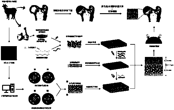
Composite scaffold for hip articular cartilage repair and preparation method of composite scaffold
A technology of cartilage repair and composite scaffold, applied in the direction of hip joints, joint implants, joint implants, etc., can solve the problem of high product brittleness, mechanical strength that cannot meet clinical mechanical support requirements, and difficulty in achieving cartilage microenvironment and osteogenesis Effective isolation of microenvironment and other problems to prevent cartilage ossification and maintain stability
- Summary
- Abstract
- Description
- Claims
- Application Information
AI Technical Summary
Problems solved by technology
Method used
Image

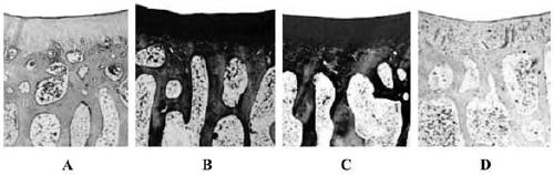
Examples
Embodiment 1
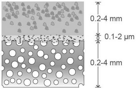
[0033] Example steps for preparing porous magnesium stents by infiltration casting method: put spherical sodium chloride crystal particles with a size of 700-800 μm into a mold with an inner diameter of 50 mm and a height of 50 mm, put the mold into a vacuum heat treatment furnace and sinter at a constant temperature of 700 ° C for 12 hours, Cooling with the furnace to obtain the open-pore porous sodium chloride preform; pour the Mg-3wt.%Nd-0.2wt.%Zn-0.5wt.%Zr alloy melt into the mold cavity with the open-pore porous sodium chloride preform , under the pressure of 2MPa, the pressure seepage casting is carried out; the outer skin of the sodium chloride-magnesium alloy composite structure is removed by a lathe, and the open-pore porous magnesium alloy can be obtained by washing with tap water for 1 hour, which is further processed into a pot-shaped porous magnesium alloy by mechanical processing.
[0034] Example steps of calcium phosphorus coating on the surface of porous magnes...
Embodiment 2
[0043] Example steps for preparing porous magnesium stents by 3D printing method: 3D printing process parameters are: magnesium powder is spherical powder, particle size is 15-45 μm, powder coating thickness is 30 μm, laser power is 80W, exposure time is 20 μs, laser scanning point spacing 30μm, the line spacing is 30μm, and the printing process is carried out under the protection of argon.
[0044] Example steps of calcium phosphorus coating on the surface of porous magnesium stent: put the porous magnesium alloy prepared above into KH containing 0.025M 2 PO 4 and 0.025M Ca(NO 3 ) 2 The reaction solution was put into a drying oven and reacted at 80°C for 12 hours; the residual reaction solution was removed by cleaning with ultrapure water in an ultrasonic cleaner for 10 minutes, and a porous magnesium alloy with a uniform calcium-phosphorus coating on the surface was obtained.
[0045] The nano-hydroxyapatite powder was prepared into a slurry, and about 2.5 grams was evenl...
Embodiment 3
[0054] Example steps for preparing porous magnesium stents by infiltration casting method: put spherical sodium chloride crystal particles with a size of 700-800 μm into a mold with an inner diameter of 50 mm and a height of 50 mm, put the mold into a vacuum heat treatment furnace and sinter at a constant temperature of 700 ° C for 12 hours, Cooling with the furnace to obtain the open-pore porous sodium chloride preform; pour the Mg-3wt.%Nd-0.2wt.%Zn-0.5wt.%Zr alloy melt into the mold cavity with the open-pore porous sodium chloride preform , under the pressure of 2MPa, the pressure seepage casting is carried out; the outer skin of the sodium chloride-magnesium alloy composite structure is removed by a lathe, and the open-pore porous magnesium alloy can be obtained by washing with tap water for 1 hour, which is further processed into a pot-shaped porous magnesium alloy by mechanical processing.
[0055] Example steps of calcium phosphorus coating on the surface of porous magnes...
PUM
| Property | Measurement | Unit |
|---|---|---|
| Thickness | aaaaa | aaaaa |
| Thickness | aaaaa | aaaaa |
| Thickness | aaaaa | aaaaa |
Abstract
Description
Claims
Application Information
 - R&D
- Intellectual Property
- Life Sciences
- Materials
- Tech Scout
- Unparalleled Data Quality
- Higher Quality Content
- 60% Fewer Hallucinations
Browse by: Latest US Patents, China's latest patents, Technical Efficacy Thesaurus, Application Domain, Technology Topic, Popular Technical Reports.
© 2025 PatSnap. All rights reserved.Legal|Privacy policy|Modern Slavery Act Transparency Statement|Sitemap|About US| Contact US: help@patsnap.com