4-substituent carbazole compound and electroluminescent device
An electroluminescent device and carbazole-based technology, applied in the field of organic photoelectric materials, to achieve high thermal stability, improve luminous efficiency, and easy-to-obtain raw materials
- Summary
- Abstract
- Description
- Claims
- Application Information
AI Technical Summary
Problems solved by technology
Method used
Image
Examples
Embodiment 1
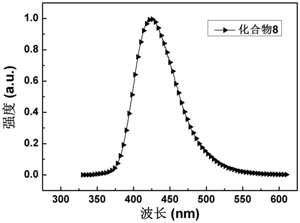
[0048] The synthesis of compound 8, the preparation method is: under nitrogen atmosphere, add 9-phenyl-9 H -carbazol-4-ol (2.59 g, 10 mmol), 2-chloro-4,6-diphenyl-1,3,5-triazine (2.67 g, 10 mmol) and 100 mL tetrahydrofuran (THF), and at 80 o C for 30 minutes. Add 50 mL of potassium carbonate (4.14 g, 30 mmol) solution under stirring, and the system continues at 80 o C for 4 h. After the reaction was completed, the heating was stopped, and the reaction was cooled to room temperature by itself. The reaction solution was poured into ~200 mL water and washed with CH 2 Cl 2 extraction. The organic phase was dried and concentrated to obtain a crude product, which was further recrystallized from ethyl acetate to obtain 3.67 g of white crystalline powder with a yield of 75%. MS (EI): m / z: 490.36 [M + ]. Anal.calcdfor C 33 h 22 N 4 O (%): C 80.80, H 4.52, N 11.42; found: C 80.78, H 4.55, N 11.40. Such as figure 1 In the fluorescence spectrum of compound 8 shown, the maxim...
Embodiment 2
[0052] The synthesis of compound 20, the preparation method is:
[0053] Under a nitrogen atmosphere, 1,3-dibromo-5-fluorobenzene (2.54 g, 10 mmol), 9-phenyl-9 H -carbazol-4-ol (2.59 g, 10 mmol), potassium carbonate (4.14 g, 30 mmol) and 50 mL N -Methylpyrrolidone (NMP), and heated to reflux for 6 h. After the reaction, the system was cooled to room temperature by itself. The reaction solution was poured into a large amount of water, and the white precipitate was collected by suction filtration. The filter cake was washed successively with water and methanol (50% (V / V)) to precipitate. Finally, the resulting filter cake was dissolved in an appropriate amount of dichloromethane, and further purified by column chromatography (mobile phase: petroleum ether: dichloromethane = 3:1 (V / V)) to obtain a white solid (Intermediate 1-1) 3.99 g, 81% yield. MS (EI): m / z: 493.36 [M + ]. Anal. calcd for C 24 h 15 BrNO (%): C 58.45, H 3.07, N 2.84; found: C 58.43, H 3.10, N 2.82.
[...
Embodiment 3
[0060] Fabrication of Organic Electroluminescent Devices (Organic EL Devices 1)
[0061] The hole injection layer 3, the hole transport layer 4, the electron blocking layer 5, the light emitting layer 6, the hole blocking layer 7, the electron transport layer 8, the electron injection layer 9 and the cathode 10 are sequentially formed on the preformed glass substrate 1. on the transparent anode 2 to prepare as image 3 The organic electroluminescent device shown.
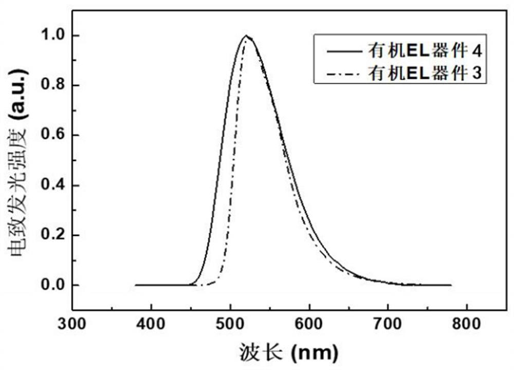
[0062] Specifically, the glass substrate formed with an ITO film with a film thickness of 100 nm was ultrasonically treated in Decon 90 alkaline cleaning solution, rinsed in deionized water, washed three times in acetone and ethanol, and baked in a clean environment until completely Moisture is removed, cleaned with UV light and ozone, and the surface is bombarded with a beam of low-energy cations. Put the glass substrate with the ITO electrode into the vacuum chamber and evacuate to 4×10 -4 -2×10 -5 Pa. Then,...
PUM
| Property | Measurement | Unit |
|---|---|---|
| thickness | aaaaa | aaaaa |
Abstract
Description
Claims
Application Information
 - R&D
- Intellectual Property
- Life Sciences
- Materials
- Tech Scout
- Unparalleled Data Quality
- Higher Quality Content
- 60% Fewer Hallucinations
Browse by: Latest US Patents, China's latest patents, Technical Efficacy Thesaurus, Application Domain, Technology Topic, Popular Technical Reports.
© 2025 PatSnap. All rights reserved.Legal|Privacy policy|Modern Slavery Act Transparency Statement|Sitemap|About US| Contact US: help@patsnap.com


