
Method for coating small particles

Inactive Publication Date: 2006-02-02
THE UNITED STATES OF AMERICA AS REPRESENTED BY THE SECRETARY OF THE NAVY
View PDF11 Cites 20 Cited by
  • Summary
  • Abstract
  • Description
  • Claims
  • Application Information

AI Technical Summary

Benefits of technology

[0018] An object of this invention is a coating method for particles which provides greater coating uniformity, greatly decreased agglomeration of the particles and greater coating continuity compared to coatings prepared by other methods.
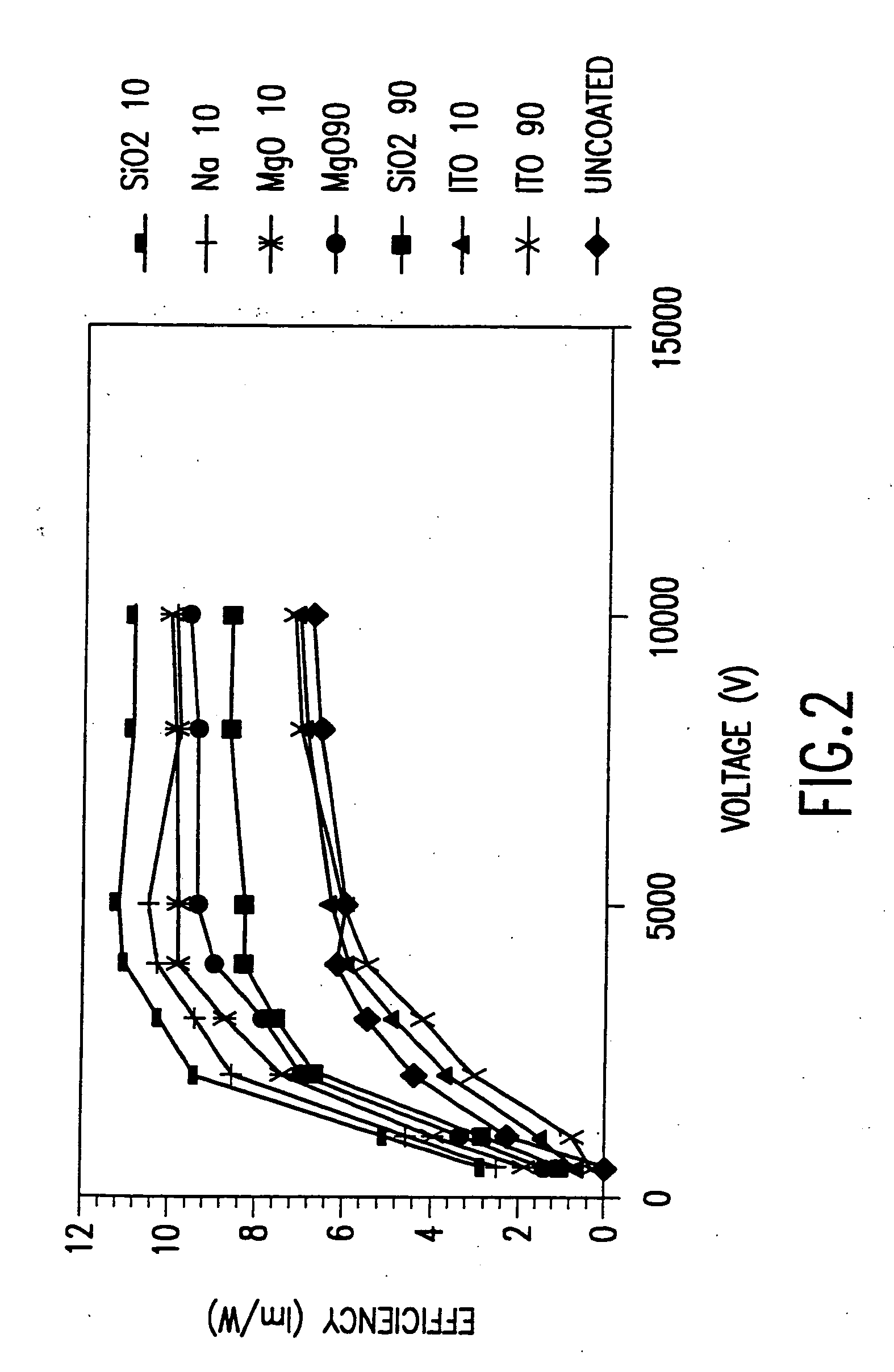
[0020] Another object of this invention is improved phosphor efficiency and service lifetime both for the phosphor particles and the electronic display device wherein the phosphor particles are used.
[0022] These and other objects can be achieved by a coating method which is characterized by preventing precipitation of the coating solution on particles to be coated until the particles enter a drying zone. Prior to passing through the zone, the particles are contained within a droplet.

Problems solved by technology

Since all of these techniques are batch type, meaning that the coating processes are not continuous and must, therefore, be filled and emptied, high product yields necessitate large processing chambers or a multitude of smaller chambers.
To-date, this process has not been used for coating particles.
If the phosphor surface is resistive, this high current density can lead to serious charging, local heating, and thermal breakdown.
Under high coulomb charging, the surface temperature of resistive phosphors increases thereby resulting in dissociation and surface degradation or aging.
Sulfur dioxide and hydrogen sulfide gases evolve from the phosphor surface and can damage the field emitters.
The longer address times associated with the high current densities used in field emission displays make the conditions worse and result in severe current saturation and phosphor degradation.
Hence, the phosphors currently used in field emission displays have very poor efficiency and service lifetimes.
However, the nanocrystalline quantum dot phosphors have very large surface areas that result in electron traps from impurities at the surface and the traps reduce the observed efficiency of the nanophosphors.
This results in a batch type process that does not readily lend itself to industrial scale-up.
Sol-gel coating methods also suffer from the need to exercise considerable care in maintaining exact pH and temperature conditions to prevent precipitation of sol-gel phases.
Furthermore, the sol-gel phase may not nucleate on the powder particles thereby producing poor coatings and individual particles of the gel phases.
Presently, the phosphors do not meet this standard.

Method used


Image

  • Method for coating small particles
  • Method for coating small particles
  • Method for coating small particles

Examples


example 1

[0050] This example details the steps to make a non-metallic indium tin oxide electrically conducting coating on a microcrystalline phosphor.

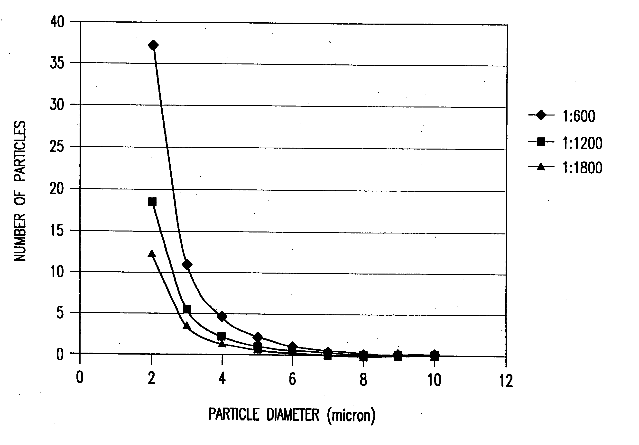
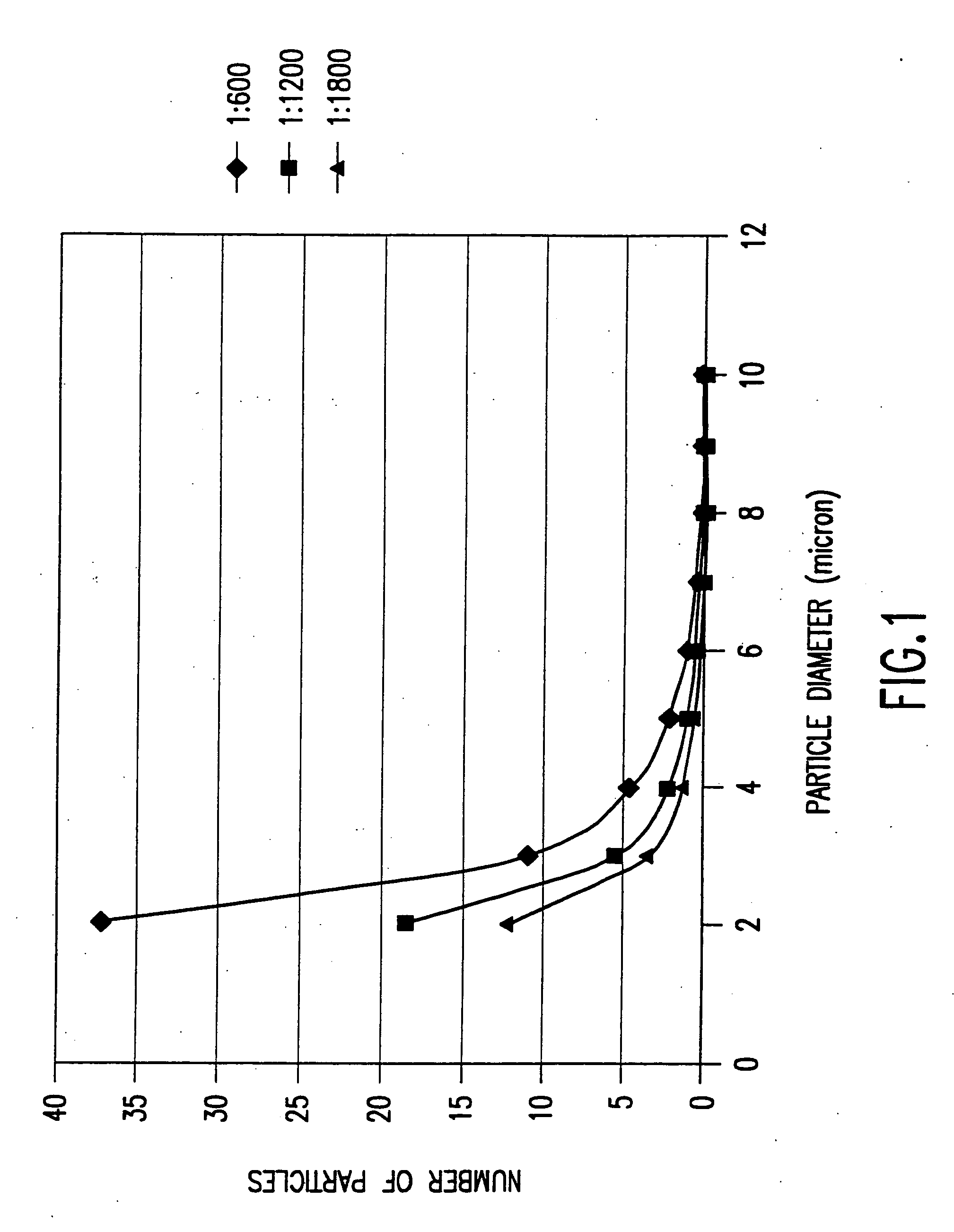
[0051] In this case, a 90 nm (15 wt %) indium tin oxide coating on a Nichia ZnS:Ag,C1 phosphor particles composed of a mixture of particles of 1-7 microns in diameter and agglomerates 3-9 microns in diameter. A precursor solution was made by mixing in 250 ml of isopropyl alcohol, 1.1 g indium methyl (trimethyl) acetyl acetate and 0.054 g tin isopropoxide. Since the indium and tin alkoxides are not stable in the presence of water, the reaction was carried out in isopropanol that was previously distilled in the presence magnesium to remove any dissolved water from the solvent.

[0052] A standard precursor solution “A” of 1.1 g of liquid indium methyl (trimethyl) acetyl acetate and 0.054 g solid tin isoporoxide in 250 ml of isopropanol was prepared in a dry box and sealed. Once the alkoxides are in solution, they do not react with water at tempera...

example 2

[0054] This example details the steps to make non conductive 90 nm thick SiO2 coatings on ZnS:Ag, C1 phosphor particles described in Ex. 1.

[0055] A stock solution was made by mixing 0.08 ml tetraethyl orthosilicate, 30 ml ethanol, 0.2 ml water and 0.62 ml hydrochloric acid. One gram of the same phosphor particles as in Ex. 1 was mixed with 2.1 m. of the stock solution and 600 ml ethanol. The slurry, at room temperature and at pH of 4.2, was sprayed into a drying zone maintained, as in Ex. 1, at 350° C. and heat-treated at 450° C. for 2 hours. X-ray diffraction of the coated powder showed the presence of ZnS and a broad amorphous hump from SiO2. Scanning electron microscope investigation showed the presence of a coating on the particles while energy dispersive x-ray analysis showed the presence of Zn, S, Si and O. Immersing the coated and un-coated phosphor particles in 0.1 molar and 12 molar hydrochloric acid was used to determine continuity of the coating. After 10 minutes, the un...

example 3

[0056] This example demonstrates the application of a hybrid coating on phosphor particles.

[0057] The hybrid coating was formed on the phosphor particles of Ex. 1 by first coating the particles with a 90 nm thick layer electrically non-conducting silicon dioxide, as in Ex. 2, and then coating the coated particles with a 90 nm thick layer of electrically conducting indium tin oxide, as in Ex. 1.


PUM


Abstract

The coating method includes the steps of dissolving coating precursor(s) in a solvent to form a precursor solution: adding with mixing a miscible diluent to the precursor solution to form a coating solution; admixing solid particles to the coating solution to form a coating slurry, with the particles surrounded with the coating solution; spraying the coating slurry to form droplets containing at least one particle; passing the droplets through a drying zone where the droplets are dried and form dry particles coated with a coating material formed from the coating precursor(s); heat-treating the coating material on the particles emanating from the drying zone to remove volatile matter on the coating material, to improve integrity of the coating material and / or to effect another objective; and collecting dry coated particles.

Description

REFERENCE TO RELATED PATENT APPLICATION [0001] This is a continuation patent application of application Ser. No. 09 / 699,396 entitled “Method for Coating Small Particles” filed Oct. 31, 2000.BACKGROUND OF THE INVENTION [0002] 1. Field of the Invention [0003] This invention pertains to a method for coating particles. [0004] 2. Description of Related Art [0005] Particles can be coated using a variety of techniques including fluidized bed, sol-gel, sputtering and evaporation. Since all of these techniques are batch type, meaning that the coating processes are not continuous and must, therefore, be filled and emptied, high product yields necessitate large processing chambers or a multitude of smaller chambers. Spray drying has been used to produce powders from precursor solutions requiring chemical reactions or from slurry mixes of the final components. Marsh U.S. Pat. No. 4,713,233 used spray drying to produce porous oxide powders from alkoxide solutions. To-date, this process has not b...

Claims


Application Information

Patent Timeline
IPC IPC(8): B05D7/00
CPCB01J2/006C09K11/584C09K11/02B01J2/04
Inventor BAYYA, SHYAM S.VILLALOBOS, GUILLERMO R.SANGHERA, JASBINDER S.AGGARWAL, ISHWAR D.
Owner THE UNITED STATES OF AMERICA AS REPRESENTED BY THE SECRETARY OF THE NAVY
Learn More