Methods and devices to ameliorate vascular obstruction

a vascular obstruction and vascular technology, applied in the field of methods and devices to ameliorate vascular obstruction, can solve the problems of preventing affecting the treatment effect, so as to prevent the appearance of clinical or esthetical symptoms, and improve the treatment effect.

Active Publication Date: 2019-11-14
WALZMAN DANIEL EZRA
View PDF0 Cites 2 Cited by
  • Summary
  • Abstract
  • Description
  • Claims
  • Application Information

AI Technical Summary

Benefits of technology

[0154]The first invention is a simultaneous rotating, irrigating, aspirating and macerating device. It provides a safe and reliable means of applying a simultaneous combination of irrigation, aspiration and maceration to a thrombi or similar material.
[0155]More particularly, the present invention has the following novel characteristics: combining the simultaneous irrigation, aspiration, and maceration; combining the simultaneous irrigation and aspiration to reverse flow, independent of maceration; combining the simultaneous irrigation and aspiration to reverse flow, independent of maceration, and retrieving clots by removing the bulk of the clot, and the induced flow reversal by the combination of simultaneous irrigation and aspiration make sure any clot pieces that break free are removed from the body via the aspiration, rather than embolizing distally and causing permanent tissue ischemia; using a balloon mounted aspiration catheter, designed to use at the face of an arterial thrombus, to occlude a vessel and facilitate flow reversal via aspiration and simultaneous distal irrigation; using a filter-tip aspiration catheter—for use in most venous and dialysis av graft de-clot cases; using the present with addition of ivus to monitor flow and clot build-up at the tip of the catheter (particularly the preferred embodiment of the present invention, at the catheter tip in the filter-tip aspiration catheter version); using the present invention (particularly in the aspiration catheter, balloon mounted, and / or filter-tip aspiration catheter) with the addition of a vibrational wire in or distal to the catheter, to break up the clot to avoid the aspirating catheter becoming clogged with large pieces of clot; and using the sinusoidal hypo-tube embodiment of the present invention that has an eggbeater like-maceration effect, while simultaneously irrigating into and beyond the clot and aspirating to remove the clot. The present invention's vibrational wire may be used with any aspiration catheter and / or balloon mounted aspiration catheter as well.
[0161]Said aspirating causes a third difficulty which is the collapse of said vessel. The present invention unlikely any prior are prevents said vessel collapse by replacing the mass of the target clot with material such as saline solution while simultaneously which removing said mass of the target clot.
[0162]More particularly, the present invention simultaneously irrigates aspirates and cuts clots. The irrigation both expands the vessel surrounding a targeted clot and replaces material removed by the present inventions rotating cutting element. The aspiration element removes both clot elements and excess fluid to prevent the vessel from exploding.
[0167]Additionally, the present invention can have additional side loops that can macerate the clot when the catheter is rotated. Aspiration can also be applied to the catheter, which can allow aspiration through the side hole and or through the end hole. If aspiration through the end hole only is desired then the side hole can be withdrawn into a sheath so that there is no aspiration on the side hole and all aspiration forces on the end hole. Alternatively, an actively controlled valve can close said side hole.
[0170]There is a critical advantage to this device in that allows rapid restoration of temporary flow of blood through a blockage to avoid ischemic injury, with immediate restoration of a degree of flow beyond a clot. This will allow additional time to remove or dissolve the clot while allowing flow to the at-risk tissue. Additionally, in the case of pulmonary emboli which are large, there is an additional issue of heart strain due to the lack of outflow from the right side of the heart. The temporary bypass catheter described here can also help relieve such heart strain by allowing outflow from the right heart past said clot when there are large pulmonary emboli in the main pulmonary arteries.

Problems solved by technology

The application of irrigation alone into the clot would tend to propagate any loose pieces—whether they are existing loose pieces or lose pieces created by maceration.
Once they get that far distal, they will clog the capillary beds, cannot be retrieved, and will cause permanent ischemic injury to the tissues.
Venous cases have a further disadvantage that the vessels with thrombus are typically much larger, so if continuous simultaneous aspiration was applied, the patient would have massive blood loss.
If it did exist and aspiration was applied continuously, in many of these cases there could be massive, often life-threatening, blood loss.
In arterial thrombectomy cases irrigation is not used with the aspiration because in smaller arteries there is a technical / engineering challenges of making a device small enough to effectively irrigate through and macerate, while not functionally obstructing the aspiration catheter (if the device fills too much of the aspiration catheter, the effective diameter of the aspiration catheter is reduced tremendously.
In arterial thrombectomy cases irrigation Aspiration may lead to the collapse of a blood vessel.
For reasons that are not entirely understood, the vessel wall can become fatigued and abnormally weak and possibly rupture.
The mass effect of an intracerebral hematoma may compromise the blood supply of adjacent brain tissue; or SAH may cause reactive vasospasm of cerebral surface vessels, leading to further ischemic brain damage.
It generally is recognized that these systems are somewhat artificial distinctions and do not reflect accurately the coagulation cascades that occur in vivo.
Since most arterial thrombi occlude the vessel in which they occur, they often lead to ischemic necrosis of tissue supplied by that artery, i.e., an infarct.
In atrial fibrillation, disordered atrial rhythm leads to slower blood flow and impaired left atrial contractility, which predisposes to formation of mural thrombi in atria.
Those venous thrombi that are large or those that have propagated proximally are a significant hazard to life, since they may dislodge and be carried to the lungs as pulmonary emboli (Id).
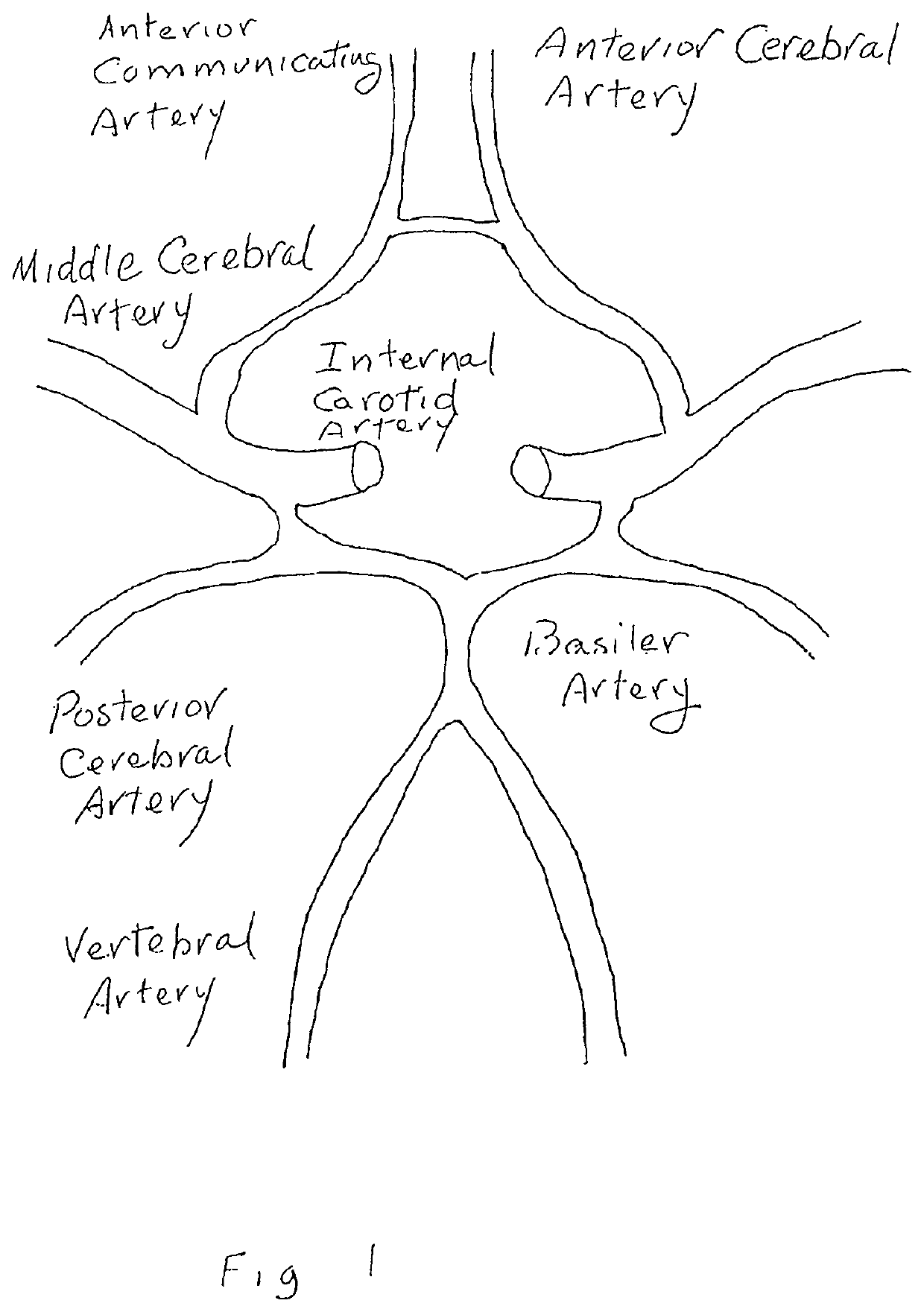
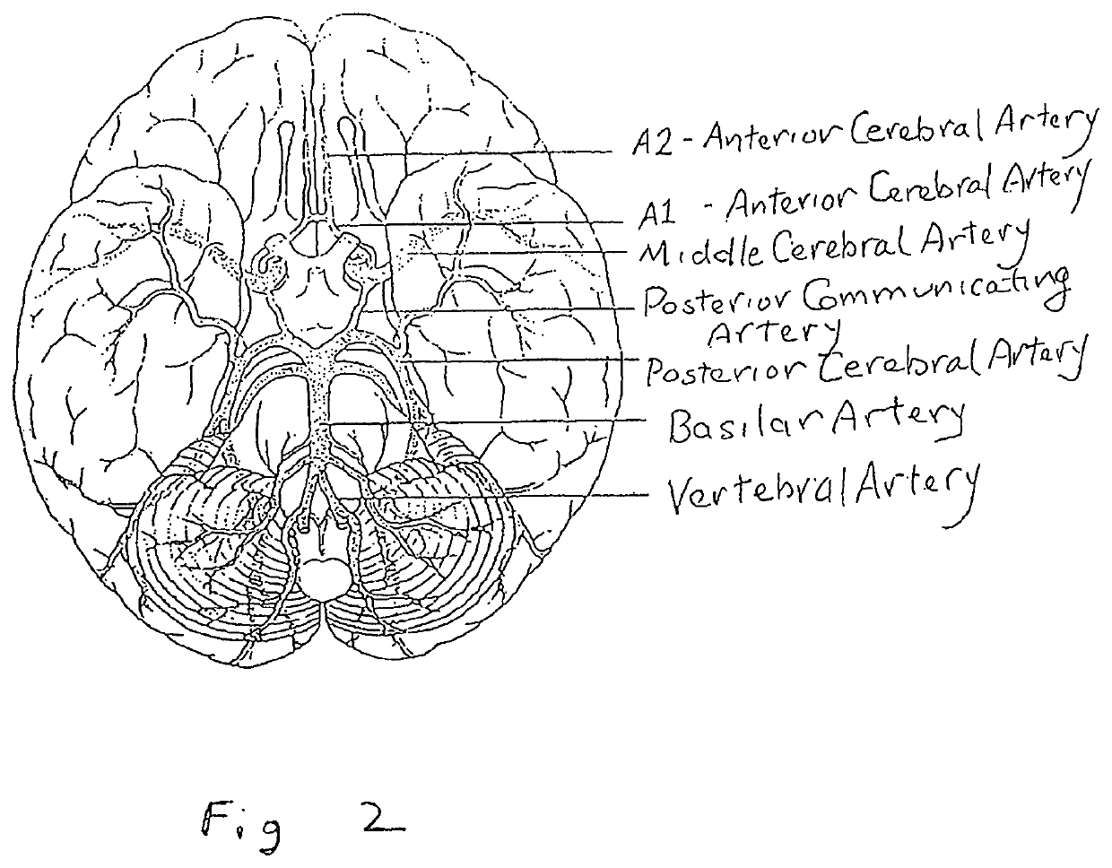
The occlusion of different cerebral vessels results in diverse neurologic deficits caused by stroke.
For example, occlusion at the trifurcation of the middle cerebral artery deprives the parietal cortex of circulation and produces motor and sensory deficits.
The latter often results from systemic hypotension (e.g., shock), and produces infarction in the border zones between the distributions of the major cerebral arteries.
If prolonged, severe hypotension can cause widespread brain necrosis.
This will eventually lead to hemorrhagic necrosis and vasogenic edema in the affected area.
Venous sinus thrombosis in the brain is a potentially lethal complication of systemic dehydration, phlebitis, obstruction by a neoplasm, or sickle cell disease.
Because venous obstruction causes stagnation upstream, abrupt thrombosis of the sagittal sinus results in bilateral hemorrhagic infarctions of the frontal lobe regions.
However, the use of fibrinolytic therapy comprises many drawbacks, including, without limitation, allergic reactions, embolism, stroke, and reperfusion arrhythmias, among others.
In addition, fibrinolytic agents have limited efficacy in certain conditions.
For example, although tPA is an accepted treatment for treatment of acute ischemic stroke, the drug's ability to recanalize a vessel is poor in some cases.
In some instances, fibrinolytic agents cannot be used at all.
Distal thrombectomy is a technically difficult procedure (Singh P. et al.
Despite good clinical outcome, limitations of this device include operator learning curve, the need to traverse the occluded artery to deploy the device distal to the occlusion, the duration required to perform multiple passes with the device, clot fragmentation and passage of an embolus within the bloodstream (Meyers P. M. et al.
These stents are not ideal for treating intracranial disease due to their rigidity which makes navigation in the convoluted intracranial vessels difficult (Singh P. et al.
Drawbacks of this method include delayed in-stent thrombosis, the use of platelet inhibitors which may cause intracerebral hemorrhage (ICH) and perforator occlusion from relocation of the thrombus after stent placement (Samaniego E. A. et al Front Neurol.
These include the requirement for double anti-platelet medication, which potentially adds to the risk of hemorrhagic complications, and the risk of in-stent thrombosis or stenosis.
However, there is a general reluctance to puncture the right brachial artery due to the need to navigate through the innominate artery and arch and due to the risk for complications such as direct nerve trauma and ischemic occlusion resulting in long-term disability (Alvarez-Tostado J. A. et al.
Despite the potential to diminish procedure time and to improve recanalization rates, drawbacks to using these devices remain.
Thus, at present, there does not appear to be a universally superior mechanical thrombectomy device that provides sufficient aspiration force without obstructing aspiration, is manageable in terms of size and flexibility, and is quick / easy to remove while preventing emboli from going to end organs.
At the point of an aneurysm, there is typically a bulge, where the wall of the blood vessel or organ is weakened and may rupture.
As blood flows within the parent artery with an aneurysm, divergence of blood flow, as occurs at the inlet of the aneurysm, leads to dynamic disturbances, producing increased lateral pressure and retrograde vortices that are easily converted to turbulence.
Approximately 0.14% of the United States population has an intracranial AVM that poses a significant risk and represents a major life threat, particularly to persons under the age of 50 years.
However, the presence of a brain AVM in the normal circulation introduces a second abnormal circuit of cerebral blood flow where the blood flow is continuously shunted under a high perfusion pressure through the AVM, possessing a low cerebrovascular resistance and low venous pressure.
The clinical consequence of the abnormal shunt is a significant increase in blood returning to the heart (approximately 4 to 5 times the original amount, depending on the diameter and size of the shunt), resulting in a dangerous overload of the heart and cardiac failure.
As the plaques form, the walls become thick, fibrotic, and calcified.
High wall shear stress mechanically damages the inner wall of the artery, initiating a lesion.
The presence of atherosclerotic lesions introduces an irregular vessel surface, resulting in turbulent blood flow, thus causing the dislodgment of plaques of varying size into the bloodstream.
Atrial fibrillation weakens the cardiac wall and introduces abnormalities in the physiological function of the heartbeat, which ultimately result in reduced systemic pressure, conditions of ischemia and stroke.
The clip remains in place, causing the aneurysm to shrink and permanently scar.
Emboli can originate from distant sources such as the heart, lungs, and peripheral circulation, which could eventually travel within the cerebral blood vessels, obstructing flow and causing stroke.
For reasons that are not entirely understood, the vessel wall can become fatigued and abnormally weak and possibly rupture.
The mass effect of an intracerebral hematoma may compromise the blood supply of adjacent brain tissue; or SAH may cause reactive vasospasm of cerebral surface vessels, leading to further ischemic brain damage.
The counterforce may be due to a lack of available space to insert the last coil.

Method used


Image

  • Methods and devices to ameliorate vascular obstruction
  • Methods and devices to ameliorate vascular obstruction
  • Methods and devices to ameliorate vascular obstruction

Examples


Embodiment Construction

[0210]The present invention includes at least one method for the simultaneous use of two devices. The first device is capable of simultaneous rotation, irrigation, aspiration, and maceration of a clot or blockage. The second is a bypass catheter. Below is a detailed description of each used in the methods disclosed.

[0211]FIG. 3 shows one aspect of an endovascular device of the described method. According to one possible configuration, FIG. 3 illustrates a side view of a microcatheter 100 with side holes 110 located around the circumference of the distal end 120 of the microcatheter 100. According to some embodiments, the microcatheter 100 further comprises a front hole 140 located at a tip of the distal end 120 of the microcatheter and a rear hole 150 located at a tip of the proximal end 130 of the microcatheter. Rear hole 150 is capable of receiving a fluid from outside a patient's body, and each of the side holes 110 and the front hole 140 are capable of ejecting fluid out of the ...


PUM


Abstract

Methods for removing blockages and preventing thromboembolic injuries, by advancing to a blockage a first tubular, endovascular device receiving irrigating fluid through a proximal opening, having a circumferential wall, lumen, at least one distal side hole oriented angularly to a distal opening; ejecting fluid from the side hole(s) to irrigate a blockage; introducing a second catheter for aspiration, comprising a circumferential wall having a proximal and distal opening, a flared, semi-permeable filter at the distal end for removal of emboli through the second lumen; advancing the second device to a blood vessel receiving blood from the blocked vessel, aspirating the blockage, axially rotating the first endovascular device having at least one half-loop to macerate an obstruction, capturing and removing emboli from the blockage through the second endovascular device which prevents emboli from causing further blockage of blood vessels. Variants of said method including a third rotatable device.

Description

CROSS-REFERENCE(S)[0001]This is a continuation-in-part claiming priority to continuation-in-part (C-I-P) application Ser. No. 16 / 125,691 filed Sep. 8, 2018 (8 Sep. 2018), which claims priority to C-I-P application Ser. No. 15 / 731,478 filed Jun. 16, 2017 (16 Jun. 2017), which in turn claims priority to C-I-P application Ser. No. 15 / 530,898 filed Mar. 20, 2017 (20 Mar. 2017), which claims priority to nonprovisional application Ser. No. 15 / 258,877 filed Sep. 7, 2016 (7 Sep. 2016); and further claims the benefit of nonprovisional utility application Ser. No. 15 / 732,953 filed Jan. 16, 2018 (16 Jan. 2018), the contents of all of which are incorporated by reference herein in their entirety.FIELD OF THE INVENTION[0002]The present invention provides methods for using two medical devices in combination during vascular procedures. The first device employs the simultaneous application of irrigating, aspirating and macerating for the purpose of safely and effectively performing thrombectomy or t...

Claims


Application Information

Patent Timeline
Patent Type & Authority Applications(United States)
IPC IPC(8): A61F2/01A61M25/00A61B17/22A61B17/3203A61B17/3207A61B8/06A61B8/12
CPCA61B17/320783A61B2090/3966A61B2017/22039A61B2017/22079A61M25/0026A61B17/22A61B17/32037A61M25/007A61B17/2202A61M2025/0042A61B17/320758A61B2017/320716A61M25/0032A61M2025/1052A61M25/0068A61B2017/00955A61B2090/3784A61F2/013A61B2017/22051A61F2002/011A61B8/06A61B8/12A61B8/0891A61B2217/007A61M25/0021A61B2017/320775A61B2017/00876A61B2217/005A61F2002/018A61B2017/320733A61B17/3207A61B2017/22067A61B2017/22084A61F2/011
Inventor WALZMAN, DANIEL EZRA
Owner WALZMAN DANIEL EZRA
Why Eureka
Try Eureka