
Implant with ceramic coating, method of forming an implant, and method of applying a ceramic coating

a technology of ceramic coating and implant, applied in the field of metal implants, can solve the problems of compromising the coating barrier properties, unable to provide the properties of a strong physical barrier, and serious health problems

Pending Publication Date: 2021-11-04
CAMBRIDGE NANOCERAMIX LTD
View PDF0 Cites 2 Cited by
  • Summary
  • Abstract
  • Description
  • Claims
  • Application Information

AI Technical Summary

Benefits of technology

The patent looks at how coatings can be formed on metal implants using electrochemical oxidation. These coatings have advantages over other methods like plasma spraying and electrodeposition. The oxide coating is formed by conversion of the metal substrate into the oxide, making it stronger and more adhesive to the metal. The patent also discusses the use of biomimetic apatite coatings on micro-arc oxidized titanium, which have high hardness and can provide anti-bacterial properties. The presence of zirconium oxide, magnesium oxide, and titanium oxide in the coating can also be introduced as nanoparticles.

Problems solved by technology

This may lead to serious health problems because, e.g. vanadium ions have been found to cause cytotoxic effects and adverse tissue reactions, while aluminium ions have been associated with neurological disorders (H. C. Choe, Nanotubular surface and morphology of Ti-binary and Ti-ternary alloys for biocompatibility, Thin Solid Films 519 (2011) 4652-4657).
HA is known to promote osseointegration but does not provide properties of a strong physical barrier.
But such a high porosity compromises the coating barrier properties, reducing its ability to prevent implant metal leaching into peri-implant tissue.
Although this method does not provide a highly convoluted surface required to enhance implant osseointegration.

Method used


Image

  • Implant with ceramic coating, method of forming an implant, and method of applying a ceramic coating
  • Implant with ceramic coating, method of forming an implant, and method of applying a ceramic coating
  • Implant with ceramic coating, method of forming an implant, and method of applying a ceramic coating

Examples


example 1

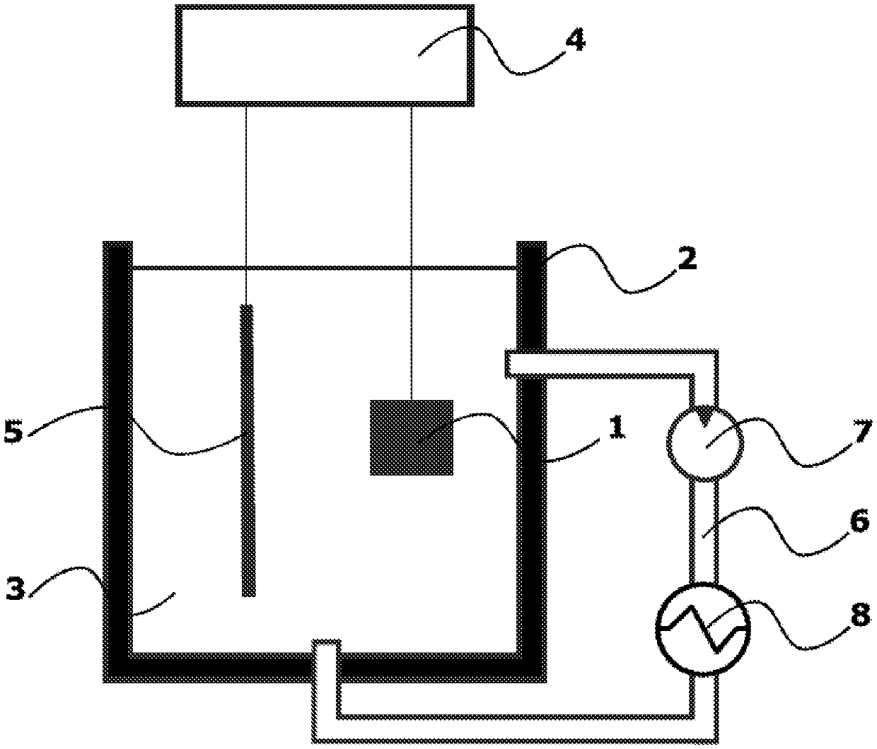
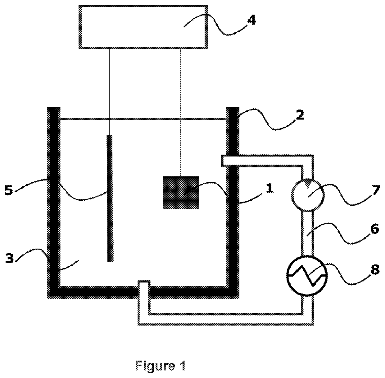
[0146]Dental implant was made of titanium grade 5 alloy (Ti-6Al-4V) rod by turning. The surface was subsequently etched in a solution of hydrofluoric acid HF and hydrochloric HCl acid. Electrochemical oxidation was conducted in an electrolytic apparatus as described above and illustrated in FIG. 1. Total coated implant surface area was 0.06 dm2. The apparatus comprised a tank containing an electrolyte, and the implant and an electrode were coupled to a pulse power supply as illustrated in FIG. 1. The substrate and the electrode were arranged in contact with the electrolyte. The electrolyte was an aqueous solution containing 1.5 g / L of zirconium sulphate Zr(SO4)2, 2 g / L potassium pyrophosphate K4P2O7, 0.4 g / L potassium hydroxide KOH and 2 g / L zirconium oxide ZrO2 nano-powder, forming a stabilised colloidal solution.

[0147]The Pulse Generator applied a sequence of electrical pulses of alternating polarity between the substrate and the electrode. Pulse repetition frequency was 3 kHz. Pu...

example 2

[0159]Magnesium alloy AZ71 was used for making a biodegradable bone implant. The implant was manufactured by die casting and cleaned in alkaline bath. Ceramic coating was applied in order to provide slower implant weight loss and reduction in Mg alloy ion release in the blood plasma.

[0160]Electrochemical oxidation was conducted in an electrolytic apparatus as described above and illustrated in FIG. 1.

[0161]The electrolyte was an aqueous solution containing 2 g / L sodium fluoride, 2.5 g / L zirconium sulphate Zr(SO4)2, 3 g / L potassium pyrophosphate K4P2O7, 2.5 g / L potassium hydroxide KOH.

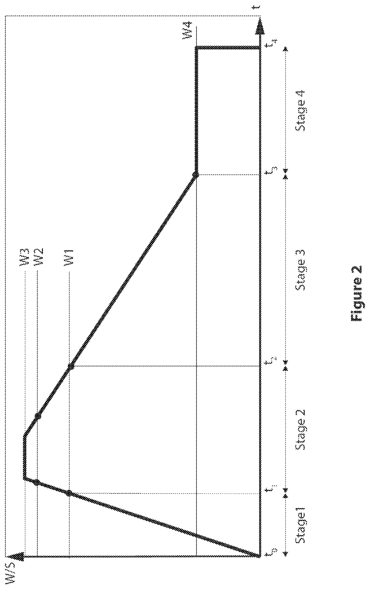
[0162]The 4 stage oxidation process lasted 14 min and it included stage one of 1 min duration, stage 2 of 4 min, stage 3 of 6 min and stage 4 of 3 min.

[0163]Formed coating contained oxides of magnesium MgO and zirconium ZrO2 and crystalline zirconium potassium phosphate of kosnarite type KZr2(PO4)3.

[0164]Formed coating had average thickness of 8 micrometres and roughness Ra=1.2 micrometres.

example 3

[0165]Pure tantalum Ta was used for making a porous intraosseous implant by additive manufacturing technique of 3D printing. After manufacturing, the implant was etched in a solution of nitric HNO3 and hydrochloric HCl acids.

[0166]Electrochemical oxidation was conducted in an electrolytic apparatus as described above and illustrated in FIG. 1.

[0167]The electrolyte was an aqueous solution containing 2 g / L of zirconium sulphate Zr(SO4)2, 2 g / L sodium pyrophosphate Na4P2O7, 0.5 g / L sodium hydroxide NaOH, 0.1 g / L silver sulphate and 3 g / L hydroxyapatite HA nano-powder, forming a stabilised colloidal solution.

[0168]The 4 stage oxidation process lasted 26 min and it included stage one of 3 min duration, stage 2 of 8 min, stage 3 of 12 min and stage 4 of 3 min.

[0169]Formed coating contained tantalum pentoxide Ta2O5, zirconia ZrO2 and hydroxyapatite. Sodium zirconium phosphate NaZr2P3O12 and silver sodium zirconium phosphate AgNaO8P2Zr are present in the coating. Formed coating had average ...


PUM

PropertyMeasurementUnit
Grain sizeaaaaaaaaaa
Fractionaaaaaaaaaa

Abstract

An implant comprises a metal body having a ceramic coating comprising monoclinic and orthorhombic phases of zirconium oxide ZrO2 and at least one multi-metal phosphate from the group comprising l-IV metal phosphates. A method of forming an implant is provided. A method of applying a ceramic coating to a metal body comprises the step of electrochemical oxidation of at least a portion of the surface of a metal body in aqueous electrolyte; in which the electrolyte contains at least two elements from a group consisting of zirconium, titanium, magnesium, phosphorus, calcium, fluoride, potassium, sodium, strontium, sulphur, argentum, zinc, copper, silicon, gallium; in which electrochemical oxidation is conducted in a plasma discharge (PEO) mode for at least one interval of time, and non-discharge modes for at least two intervals of time.

Description

TECHNICAL FIELD[0001]The invention relates to metal implants with ceramic surface coatings, to methods of forming an implant, and to methods of applying a ceramic coating to a metal body.BACKGROUND[0002]Metal implants are known to benefit from coatings applied on their surface to enhance their biocompatibility, osseointegration and prevent the implant metal release into tissue (Takao Hanawa, Biofunctionalization of titanium for dental implant, Japanese Dental Science Review (2010) 46, 93-101). Different metals such as titanium (Ti), zirconium (Zr), tantalum (Ta), iron (Fe) and magnesium (Mg) and their alloys are used for medical implants. The most popular material is titanium (Ti) and its alloys, thanks to their biocompatibility.[0003]Ti Grade 5 (Ti-6Al-4V) alloy is a preferred material for implant applications due to its high mechanical strength and toughness. Ti grade 5 alloy contains 4 wt % of vanadium and 6 wt % of aluminium both being considered not biocompatible (Bartáková S. ...

Claims


Application Information

Patent Timeline
IPC IPC(8): A61L27/32A61L27/04A61L27/06A61L27/10A61L27/56A61L27/54
CPCA61L27/32A61L27/047A61L27/06A61L27/10A61L27/56A61L27/54A61L2300/606A61L2420/06A61L2420/08A61L2430/02A61L2300/406A61L2300/41A61L2300/414A61L2420/02A61L27/50
Inventor SHASHKOV, PAVELYEROKHIN, ALEKSEYUSOV, SERGEY
Owner CAMBRIDGE NANOCERAMIX LTD
Learn More