The collector
electrode mentioned above is provided on the incident surface; consequently it reduces the effective generating area of the
solar cell.
The
vacuum evaporation method has problems such as a slow
deposition rate and low
throughput, caused by the use of vacuum process, and the necessity of masking to form the linear pattern, which masking results in the loss of
metal and deposition on the masked portions.
However, these proposals have the following problems.
A) The following problems were found as a result of a long term
exposure test or by temperature-
humidity tests: a
short circuit between the upper
electrode and the lower electrode is formed at a defective part such as a pin-hole; lower conversion efficiency results from the small shunt resistance, and the yield tends to get worse.
C) The electrode disclosed by U.S. Pat. No. 4,260,429 has a problem that some portion of the electrode may have not enough bonding force to the
semiconductor element.
On some occasions, tab portion(s) of the
metal material did not have enough bonding force when adhesive connection between the
solar cell substrate and
metal tab of the collector electrode was required.
The solar cells that used electrodes as described above had a problem that a series resistance increase and a conversion efficiency decrease caused by deterioration of the bonding force occurred during the accelerated temperature-
humidity test and
heat resistance test.
E) Some problems of electrode peeling were observed with solar cells caused by poor initial bonding force between the solar
cell substrate and metal tab, and also by degradation of the bonding force between the
cell element, metal wire, and the
coating layer, affected by the
humidity and temperature.
However, in the case where a thermosetting resin was used the above mentioned electrode had a problem that it was difficult to obtain sufficient bonding force when it was formed on the solar
cell because the
cure rate of the
polymer after the
drying step was difficult to control.
Furthermore, there was no means for the selection of the curing agent for the thermosetting resin and a relatively long
curing time was required.
H) When only
thermoplastic resin was used, deformation of the electrode occurred due to thermo-
hysteresis during the lamination process after the formation of the electrode, and the following problems were observed:
line width change, partial peeling, and
position shift of the electrode.
The solar cells that used the above mentioned electrode had a problem that a series resistance increase and a conversion efficiency decrease was caused by the deterioration of the bonding force during long term
open air exposure test or temperature-humidity tests as accelerated tests.
A) Although the idea of preventing physical contact between the
metallic electrode and the
semiconductor layer was disclosed, a solution of the problem, in which the metal
ion diffuses slowly through the
conductive polymer and induces trouble, was not proposed.
C) The proposal has some limit to the electrode formation process because the procedure does not contain a
drying step and the coated wire cannot be stored.
A) Either proposal has the problem that it is difficult to obtain a
coating layer of uniform thickness and stable good electric
conductivity.
As a result the shunt resistance decreased, lower conversion efficiency results, and the yield decreases.
A) Short circuits between the upper electrode and the lower electrode are formed when an
amorphous silicon solar cell that has defective parts such as pin holes was used, and lower conversion efficiency results from the small shunt resistance, and the yield tends to get worse.
B) Series resistance of the electrode that is covered by the conductive adhesive increases due to thermo-
hysteresis because of the
dissolution or
softening of the electrode caused by the penetration of the paint
solvent.
According to experiments conducted by the inventors, the problem arising in the formation of the prior art collecting electrode, following the
coating and
drying of the wire, in environments where light and
moisture are present, was found to be caused by
electromotive force being applied to the collecting electrode, thereby causing
diffusion of ions from the metal wire to the conductive resin layer.
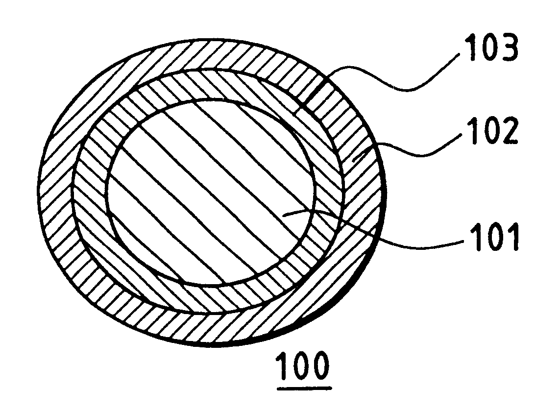
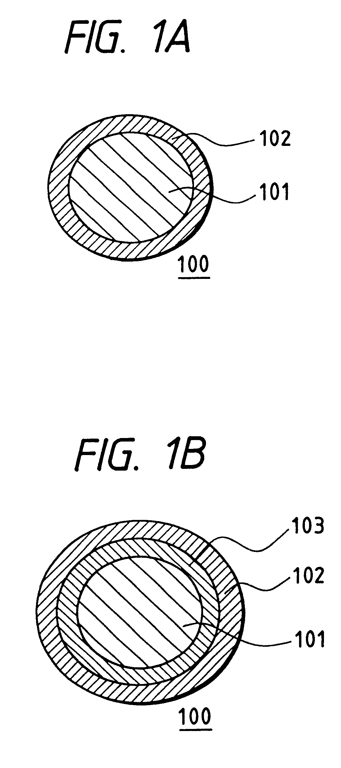
Also, the problem of
shunting occurring with the prior art collecting electrode formation process was found to be caused by the metal wire contacting the semiconductor layer or the transparent conductive film, because the conductive
resin coating consisted of only one layer.
In other words, it is not possible, with the prior art collecting electrode, to prevent the metal wire from directly contacting the semiconductor layer (i.e. without the intermediate conductive resin) during the
thermocompression bonding process and therefore, it was found that contact of the semiconductor layer and the wire was the cause of the initial decrease in yield.
In addition, we have discovered that, even if such contact was prevented, metal
ion diffusion occurred during actual usage, because of minute pores in the conductive resin, as well as the
moisture and
ion permeability of the resin itself.
We have also discovered that the problem of long-term loss of
dependability was attributed to the deterioration of
conductivity of the conductive resin, caused by oxidation of the metal wire surface (consisting of
copper, etc.), which is caused by
moisture penetration during outdoor use, because the
polymer used in laminated solar batteries is not perfectly water tight.
We have also found out that the cross-linking density of the conductive resin layer could not be controlled with respect to the
shelf life and adhesive strength of the collecting electrode.
In other words, the problem was that, when curing the polymers that form the conductive resins of the prior art collecting electrode, the resin would harden after drying, for example during storage, while the use of
thermoplastic resin was also a problem because the fluidity would become too large due to the heat applied in later processes, because the resin will not cross-link.
Enamel wires, etc. are made by coating these metal wires with insulating
varnish, but generally, it is not easy to coat metals, which are inorganic, with organic materials.
In addition, sufficient adhesive strength may not be obtained when adhering the wire, through the coating layer, to semiconductors and metals.
This problem becomes even more pronounced depending on the metal material and its
surface conditions, and we have discovered that almost no adhesive strength can be obtained when the surfaces are affected by moisture.
Wires with diameters smaller than 25 .mu.m are prone to breakage, difficult to produce, and their
power loss is larger.
Meanwhile, diameters of 200 .mu.m or more cause larger shadow loss or the surface of the photovoltaic element becomes bumpy, making it necessary to make the filler used on the
surface coating layer, such as EVA, thicker.
Thicknesses of under 1 .mu.m will make it difficult to create a uniform coating and pin-holes will occur, rendering it insufficient as a barrier.
On the other hand, thicknesses of over 15 .mu.m are not desirable because they are difficult to peel and shadow loss becomes too great.
When the resistance is smaller than 0.1 .
OMEGA.cm, the shunt prevention function becomes insufficient and when it is greater than 100 .
OMEGA.cm, loss from electric resistance becomes too great.
The
diameter of the conductive particles should be smaller than the coating layer to be formed, but if the particles are too small the resistance at the contact points of the particles to each other becomes great, making it impossible to obtain the desired resistivity.
Resistivity will decrease as the amount of conductive particles increase, but the coating layer will lose its stability as the proportion of resin decreases.
And when the amount of
polymer is increased, the contact of the conductive particles to each other becomes faulty and will result in
high resistance.
Enamel wires, etc. are made by coating these metal wires with insulating
varnish, but generally, it is not easy to coat metals, which are inorganic, with material that contains organic material.
In addition, sufficient adhesive strength may not be obtained when adhering the wire, through the coating layer, to semiconductors and metals.
This problem becomes even more pronounced depending on the metal material and its
surface conditions, and we have discovered that almost no adhesive strength can be obtained when they are affected by moisture.
High gel ratios after the drying process will result in decreased adhesive strength during the formation of the collecting electrode.
In addition, low
sol ratios of the conductive resin layer of the collecting electrode formed by thermocompression, may result in decreased
dependability when subjected to moisture.
Resistivity will decrease as the amount of conductive particles increase, but the coating layer will lose its stability as the proportion of resin decreases.
Also, when the polymers are increased, the contact between the conductive particles becomes faulty and results in
high resistance.
Thicknesses of under 1 .mu.m make it difficult to create a uniform coating and pin-holes will occur, rendering it insufficient as a barrier.
On the other hand, thicknesses of over 15 .mu.m are not desirable because they are difficult to peel and shadow loss becomes too great.
When voids larger than this do exist, the
mechanical strength of the conductive adhesive deteriorates after curing.
One of the problems of production is that, in order to produce coated wire electrodes off-line and to facilitate storage until the formation of electrodes, it is difficult to control accelerated hardening of the resins, after the resin has been coated and dried on the metal wire.
In other words, whereas it has been very difficult to control accelerated hardening with other curing agents, such problems are solved by using a blocked
isocyanate as the curing agent.
Another production related problem is, that it is convenient for handling if the metal wires are wound around a
bobbin, etc. after the resin has been coated.
However, the tackiness of the coated wires made it difficult to unwind them from the
bobbin and in some cases where tackiness was strong, the coating would peel off.
Although the
diameter of a conductive particle should be smaller than the thickness of the
conductive coating layer, too small a
diameter increases resistance at the surface of the particles where they contact each other, making it impossible to obtain the desired resistivity.
If the dispersibility is poor, agglomerated particles of a high order exist to cause not only nonuniform film thickness but also unstable
conductivity.
Although increased conductive particles reduce resistivity, they decrease the ratio of resin, resulting in poor stability as a coating film.
A problem during and after the formation of electrodes on a photovoltaic element is forming of pinholes which causes leakage current to defective parts, thereby reducing the characteristics of the photovoltaic element.
Another problem is that metal wires touch the solar
cell substrate to cause
shunting during forming of electrodes.
However, the RF
plasma CVD method has problems such as the low yield of the
raw material gas
decomposition (about 10%) and the slow deposition speed (about 0.1 nm / sec. to 1 nm / sec.).

