Thermal infrared reflective pigments for coatings

a reflective pigment and thermal infrared technology, applied in vacuum evaporation coating, electrophoresis, electrolysis, etc., can solve the problems of long path length, low reflectivity of irsub>t /sub>waveband formulations, and limited use of such highly irsub>t /sub>reflective materials

Active Publication Date: 2008-11-25
QINETIQ LTD
View PDF13 Cites 21 Cited by
  • Summary
  • Abstract
  • Description
  • Claims
  • Application Information

AI Technical Summary

Benefits of technology

[0013]It is therefore an object of the present invention to provide a highly IRT reflective additive for use in paint (and other coating) formulations that substantially mitigates or overcomes the problems associated with prior art formulations of Types 1 to 3.

Problems solved by technology

However, the use of such highly IRT reflective materials is currently restricted to areas where decorative appearance is not a primary concern, for example in loft spaces and in cavity wall voids.
However, these formulations have relatively low reflectivity in the IRT waveband due to absorption in the pigment particles, multiple reflections leading to long path lengths through the organic polymer binder and poor scattering due to small differences in refractive index of the binders and conventional granular pigments at IRT wavelengths.
Reflectivities in the IRT waveband of greater than 0.3 are difficult to achieve in coloured coatings based on scattering granular pigments.
The disadvantage of Type 2 paints formed purely from appropriately sized metal flakes such as 30 μm diameter aluminium flakes is aesthetic, since they appear silver-metallic in colour when in a high IRT reflectivity formulation (or grey-metallic or ‘gold’ in the case of metal flakes based on coloured metals such as tungsten and brass respectively).
The disadvantage of this approach is that when particulate colour pigments are added to flake-containing binders, the orientation of the flakes will be disturbed so that they no longer align with each other or with the surface of the paint.
The mis-alignment reduces the IRT reflectivity achievable with the paint system due to scattering related effects.
The durability of Type 3 paints using a thin colour layer is limited since the removal of the thin colour layer through scuffing and abrasive cleaning etc. can reveal the presence of the metal reflector layer causing the paint to appear ‘silvery’.

Method used


Image

  • Thermal infrared reflective pigments for coatings
  • Thermal infrared reflective pigments for coatings
  • Thermal infrared reflective pigments for coatings

Examples


Embodiment Construction

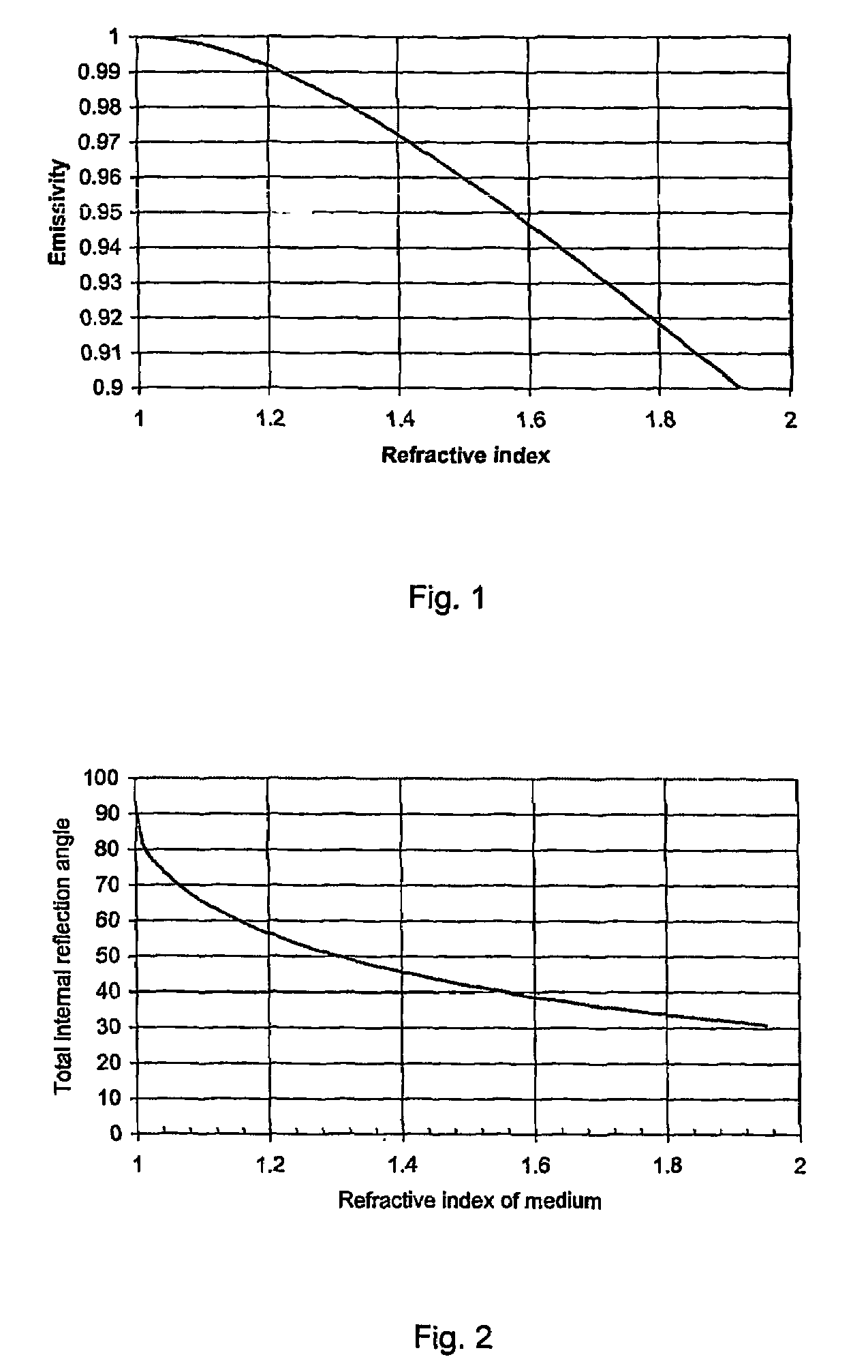
[0037]By way of background to the present invention, all bodies above OK (−273° C.) emit electro-magnetic (EM) radiation as a result of processes in their atomic and molecular structure. At temperatures encountered in human habitations (0 to 30° C.) this electromagnetic radiation is predominately at frequencies in the range of 3×10¹² to 3×10¹⁴ Hz, equivalent to a wavelength of 1 to 100 μm, commonly referred to as the ‘infrared region’ of the EM spectrum. At temperatures in the range 0-30° C. more than 90% of the radiant energy arising from a body is in the wavelength interval 3 to 50 μm, this part of the electromagnetic spectrum is called the Thermal Infrared (IRT) region.

[0038]To a first approximation, the IRT energy emitted by a surface is given by the Stephan-Boltzmann equation:

W=εσT4 Wm−2,

where ‘W’ is the radiated power, ‘ε’ is the emissivity, ‘σ’ is the Stephan-Boltzmann constant and ‘T’ is the temperature in Kelvin.

[0039]In a simplified form, Kirchoffs law relates the emissivi...


PUM

PropertyMeasurementUnit
thicknessaaaaaaaaaa
thicknessaaaaaaaaaa
thicknessaaaaaaaaaa

Abstract

This invention relates to the control of radiant thermal energy and more specifically to highly Thermal Infrared (IRT) reflective pigments for use in decorative coatings for buildings or other areas where the control of IRT energy and visual decoration are required. Control of the spread of thermal energy in domestic building through passive techniques reduces energy consumption by reducing reliance on heating in cool environments and cooling air-conditioning in warm environments. A number of paint formulations having low emissivity in the thermal infrared exist which are based on variants of conventional decorative paint fluids. There are a number of problems associated with such formulations such as susceptibility to damages and high emissivity for certain colour pigmentations. The present invention proposes a low emissivity flake (1) for use in a paint formulation which substantially overcomes the problems associated with the prior art.

Description

BACKGROUND OF THE INVENTION[0001](1) Field of the Invention[0002]This invention relates to the control of radiant thermal energy and more specifically to highly Thermal Infrared (IRT) reflective pigments for use in decorative coatings for inhabited buildings or other areas where the control of IRT energy and visual decoration are required.[0003](2) Description of the Art[0004]Control of the spread of thermal energy in domestic buildings through passive techniques reduces energy consumption by reducing reliance on heating in cool environments and cooling air-conditioning in warm environments.[0005]Convection as ‘draughts’ and conduction are widely recognised heat transport mechanisms and many materials and methods have been developed to reduce their effect on energy consumption in structures. Thermal energy may also be transported through radiative processes. Humans readily perceive conduction and convection processes but are less sensitive to radiative heat transfer from surfaces at...

Claims


Application Information

Patent Timeline
Patent Type & Authority Patents(United States)
IPC IPC(8): B32B5/16B05D7/00C25D15/02C01G19/00C09C1/64C09D5/00C09D7/62
CPCC01G19/00C09C1/644C09D5/004C09D7/1283C09D7/1291C01P2004/20C01P2004/61C01P2006/40C08K3/08Y10T428/2991C08K9/08C09C1/62C09C1/00C09D7/69C09D7/70C09D7/62
Inventor O'KEEFE, EOIN
Owner QINETIQ LTD
Why Eureka
Try Eureka