Thick-film sheet member its applied device and methods for manufacturing them

a thin film, sheet member technology, applied in the manufacture of electrode systems, tubes with screens, electric discharge tubes/lamps, etc., can solve the problems of difficulty in handling sheet members in the production process, one of the producing methods requires a large-scale installation, and the thickness of conventional sheet members is limited, etc., to achieve the effect of high degree of freedom, easy handling and easy formation

Inactive Publication Date: 2005-06-09
NORITAKE CO LTD
View PDF2 Cites 31 Cited by
  • Summary
  • Abstract
  • Description
  • Claims
  • Application Information

AI Technical Summary

Benefits of technology

[0005] The present invention was made in view of the above-described background circumstances. It is therefore an object of the invention to provide a sheet member which can be easily formed from a plurality of materials with a high degree of freedom in its pattern designing and which can be easily handled in its production process without requiring a complicated installation, and a method of producing such a sheet member. Further, it is also the object of the invention to provide devices to which the sheet member is applied, and methods of producing the devices.

Problems solved by technology

However, the conventional sheet member suffers from limitations in its thickness, dimension and configuration, due to above-described producing methods.
Further, any one of the producing methods requires a large-scaled installation, and provides a difficulty in handling the sheet member in the production process when the sheet member has a large surface area and a small thickness.
For example, where a ceramic sheet is laser machined, it is necessary to employ a laser machine which is expensive, and there are limitations in quality of the machined surface since the sheet could suffer from its deterioration depending upon the used material.
Further, the laser machining requires a large length of operation time.
Where a sheet metal is chemically etched, it is likely to be deformed or wrinkled if the sheet metal has a large surface area.
Further, where protrusions and recesses have to be formed on a surface of the sheet metal, it is necessary to carry out a half-etching operation whose process is so complicated that the quality tends to be variable.
Further, where the sheet member is used for constituting electrodes, the sheet member has to be divided into sections corresponding to the respective electrodes, thereby considerably increasing a number of the components and complicating handling of the sheet member.

Method used


Image

  • Thick-film sheet member its applied device and methods for manufacturing them
  • Thick-film sheet member its applied device and methods for manufacturing them
  • Thick-film sheet member its applied device and methods for manufacturing them

Examples


third embodiment

[0197]FIGS. 9 and 10 are a process chart for explaining another example of the method of producing the sheet member of the present invention, and a view illustrating main stages of the producing method, respectively. In the present embodiment, a patterning step 92 is provided between the thick-film-paste-layer forming step 36 and the drying step 46. FIG. 10(a) is a view showing a state after implementation of the thick-film-paste-layer forming step 36. As shown in this figure, a thick-film paste layer 94 is formed in a simple solid form without being particularly patterned. The thick-film paste layer 94 is constituted by a photosensitive resin, and is formed with, for example, a coater, film laminate or the like.

[0198] In the subsequent patterning step 92, the thick-film paste layer 94 is subjected to an exposure treatment by using an exposure mask 96 having a predetermined pattern, and is then subjected to a washing or other processing. FIG. 10(b) shows a state during the exposure...

fourth embodiment

[0199] FIGS. 11(a)-(c), corresponding to FIGS. 4(c)-(e), are views for explaining a case where a raw ceramic sheet 100 is used as the support body. In the present embodiment, the printed dielectric layer 42 and printed conductive layer 44 are formed by applying the thick-film paste onto a surface 102 of the raw ceramic sheet 100. The raw ceramic sheet 100 on which the printed layers 42, 44 are disposed is introduced into the furnace chamber 50, so that the raw ceramic sheet 100 is subjected to a firing treatment while being mounted on a setter 104. As a result of the firing treatment, the thick-film sheet (the thick-film dielectric layer 52 and thick-film conductive layer 54) is mounted on the setter 104 with the particle layer 58 being interposed between the thick-film sheet and the setter 104. As long as there is no particular problem as to the surface state and reactivity of the setter 104, the thick-film sheet 10 can be thus produced. Needless to say, it is also possible to fire...

fifth embodiment

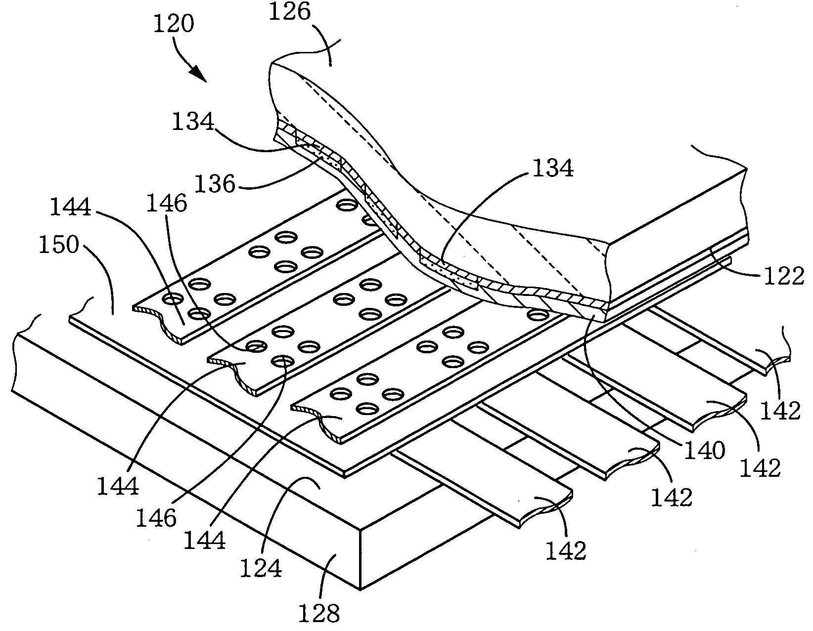
[0201]FIG. 13 is a perspective view partially in cross section of a FED 120 which is one example of a cold-cathode display device of a fourth invention. The FED 120 is produced with a production process to which a producing method of a fifth invention is applied. The FED 120 is equipped with front and back face plates 126, 128 which are substantially identical with each other in size and shape and which are disposed in parallel with each other with a predetermined spacing distance therebetween such that their respective substantially flat surfaces 122, 124 are opposed to each other. The front and back face plates 126, 128 are gas-tightly sealed at their respective peripheral portions, whereby a gastight space is formed in their inside. This gastight space is adapted to be evacuated have a reduced pressure of about 6.7×10⁻⁵ (Pa) [5×10⁻⁷ (Torr)]. In the present embodiment, the back face plate 128 corresponds to a first substrate while the front face plate 126 corresponds to a second s...


PUM

PropertyMeasurementUnit
thicknessaaaaaaaaaa
temperatureaaaaaaaaaa
conductiveaaaaaaaaaa

Abstract

A thick-film sheet member provided by a thick film which has a predetermined thickness and a predetermined thickness and a predetermined plan configuration, without the thick film being fixed to a substrate. This thick-film sheet member can be produced by (a) forming a paste film having a predetermined thickness, on a predetermined film formation surface in a predetermined pattern, and (b) peeling the paste film from the predetermined film formation surface after subjecting the paste film to a firing treatment effected at a predetermined temperature. The paste film is constituted by a thick-film material in the form of particles which are bonded together with a resin and which are sintered at the predetermined temperature.

Description

TECHNICAL FIELD [0001] The present invention relates to a thick-film sheet member which is obtained by forming a thick-film material into a sheet-like member, various devices such as a display device to which the thick-film sheet member is applied, and methods of producing them. BACKGROUND ART [0002] There is known a sheet member which is constituted by, for example, a single or plural kinds of inorganic materials, metallic materials or the like and which has a desired configuration and a thickness of about 1 (μm)-10 (mm). Where such a sheet member is constituted by the inorganic material, it is produced by first subjecting an unfired ceramic sheet prepared in accordance with a tape casting method or the like, to a machining operation such as drilling and patterning performed by, for example, laser, punching press, water / sand blasting or the like, and then firing the machined sheet, or alternatively, it is produced by first firing a ceramic sheet and then subjecting the fired sheet ...

Claims


Application Information

Patent Timeline
Patent Type & Authority Applications(United States)
IPC IPC(8): H01J9/02H01J9/14H01J9/24H01J29/02H01J31/12H05K3/20
CPCH01J9/02H01J9/14H01J9/241H05K3/207H01J31/123H01J31/126H01J31/127H01J29/02Y10T428/31504
Inventor SAKAMOTO, SUSUMUHIROSHIMA, MASAYUKIMORI, SHIGEONARAKI, EIJISATO, KOICHITAKECHI, HIROTOSHI
Owner NORITAKE CO LTD
Why Eureka
Try Eureka