At this time, if coefficient of
thermal expansion of the material of the pump case is much different from the coefficient of
thermal expansion of the material of the gear rotor set, clearance therebetween increases, reducing volume efficiency of the pump.
However, different from the valve spool and the valve case formed of
iron based material, the valve spool and the valve case formed of aluminum alloy are more susceptible to the problems of
abrasive wear, seizure and sticking caused by friction sliding of aluminum alloy members with each other.
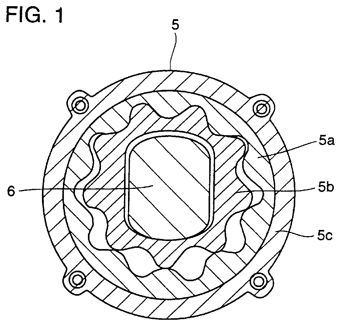
However, the gear rotor set for the
oil pump in accordance with the first prior art example suffers from the following problem.
Especially, the outer rotor is prone to seizure and wear with a
mating material at an outer
peripheral surface which slides over the pump case and at the tip of the teeth sliding over the inner rotor.
Accordingly, it is difficult to apply sintered aluminum alloy having low strength to the inner rotor to which
high torque is applied or to the outer rotor of which superior seizure resistance is required.
It is very difficult, however, to form the inner rotor or the outer rotor having sufficiently
high dimensional precision using the sintered aluminum alloy fabricated by hot
forging or hot
extrusion.
Such process increases manufacturing cost of the inner rotor and the outer rotor, presenting economical problem.
Consequently, the inner circumferential surface of the inner rotor is wore and damaged, or suffers from laminer peeling at the surface portion, caused by bearing fatigue resulting from difference in mechanical characteristics including strength,
hardness and stiffness between the steel and the aluminum alloy.
In the valve spool and the valve case to which aluminum alloy coated with hard
coating is applied, the cost is higher as compared with the conventional ones formed of
iron based material, causing economical problem.
Further, peeling and friction of hard
coating are observed when the valve spool slides.
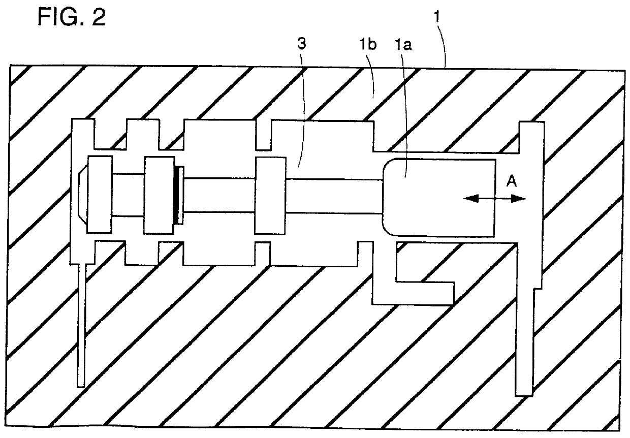
A valve having a combination of a valve spool formed of aluminum alloy subjected to
anodizing plating and a valve case formed of
iron based alloy, or a valve having the combination of a valve spool formed of an
iron based alloy and the valve case formed of an aluminum alloy subjected to
anodizing plating suffers from the following problem, because of the difference in coefficient of
thermal expansion between the valve spool and the valve case.
More specifically, when the temperature is low, clearance between the valve spool and the valve case is small, causing sticking where the valve spool cannot slide satisfactory.
Such process increases cost, while lowering reliability.
If the amount of
silicon is smaller than 5 wt %, sufficient
wear resistance, seizure resistance and the like of the sliding member cannot be ensured.
Accordingly,
processing of the ingot aluminum alloy would be difficult.
If the amount of aluminum
nitride is smaller than 0.5 wt %, however, sufficient
heat resistance and wear resistance cannot be ensured.
If the amount of aluminum
nitride exceeds 11 wt %, wear resistance is not much improved, while
machinability and
toughness of the sintered aluminum alloy are degraded.
If the amount of
magnesium is smaller than 0.05 wt %, however, reduction by
magnesium is not sufficient to uniformly generate aluminum nitride in the sintered aluminum alloy.
If the content exceeds 25 wt %, however, these characteristics are not much improved, while toughness of the sintered aluminum alloy decreases and
hardness and stiffness of the sintered aluminum alloy attain too high, making
processing of the sintered aluminum alloy difficult.
If the content exceeds 5 wt %, however, wear resistance and seizure resistance of the sliding member are not much improved, while
machinability of the sintered aluminum alloy is degraded and the sintered aluminum alloy may possibly
attack the
mating material.
If content of the lubricating component exceeds 5 wt %, however,
bonding strength of aluminum alloy
powder particles with each other as the base of the sintered aluminum alloy degrades, and therefore sufficient
mechanical strength of the sliding member cannot be ensured.
If the
porosity of the outer rotor is smaller than 3 vol % or if the
porosity of the inner rotor is smaller than 2 vol %, however, there would not be sufficient pores on the sliding surfaces to effectively prevent loss of
oil film at the sliding interface.
If the amount of aluminum nitride is smaller than 0.5 wt %, however, sufficient
heat resistance and wear resistance are not provided.
If the amount of aluminum nitride exceeds 6 wt %, wear resistance and so on are not much improved, while machinability and toughness of the valve spool are degraded.
If the hardness of the hard
coating is lower than 150 micro-Vickers hardness, the hard coating would be worn, resulting in considerable sticking, when foreign particles enter.
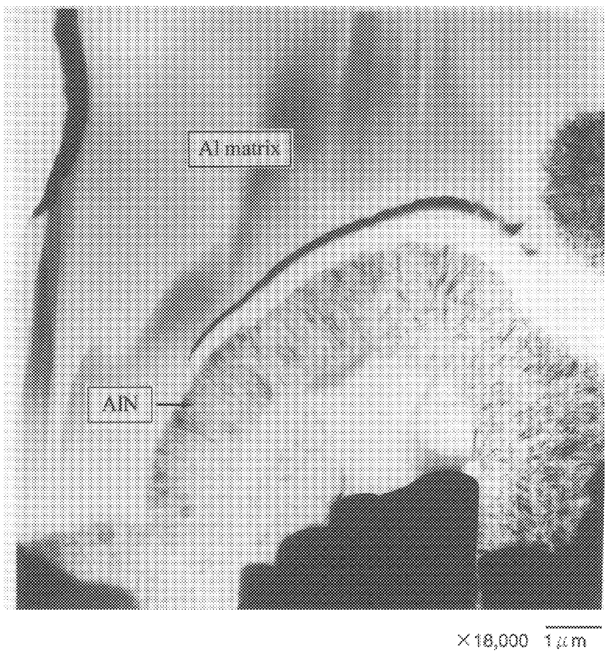
As the particles of the aluminum alloy are constrained mechanically in aluminum alloy, the effect of improving heat resistance is limited.
Further, particles of aluminum nitride fall out by friction and sliding with the
mating valve case, and the fallen particles serve as hard
abrasive powder, causing seizure and gaulling.
When the amount of
nitrogen is smaller than 0.1 wt %, that is, if the amount of aluminum nitride is smaller than 0.5 wt %, heat resistance and wear resistance of the sintered aluminum alloy are not sufficient.
If the amount of nitrogen exist 3.5 wt %, that is, if the amount of aluminum nitride exceeds 11 wt %, wear resistance of sintered aluminum alloy is not much improved, while machinability and toughness decrease, and the time for the
sintering process of the sintered aluminum alloy becomes longer, which is disadvantageous in view of economy.
If the amount of aluminum nitride is smaller than 0.5 wt %, heat resistance and wear resistance of the sintered aluminum alloy are not sufficient.
If the amount of aluminum nitride exceeds 6 wt %, wear resistance of the sintered aluminum alloy used as the valve spool is not much improved, while machinability and toughness decreased, or the time for the
sintering process of the sintered aluminum alloy becomes longer, which is disadvantageous in view of economy.
At this time, if the content of
magnesium is smaller than 0.05 wt %, reduction by magnesium is not sufficient to uniformly generate aluminum nitride.
In that case, degradation of machinability and toughness of the sintered aluminum alloy used specially as the valve spool is considerable.
Therefore, when the sintered aluminum alloy is used for the valve spool, there would be a problem of chipping of the valve spool when a
metal part is press fit into the valve spool.
If the
porosity is smaller than 2 vol %, oil is not sufficiently held at the pores, resulting in seizure and abrasive wear.
If the porosity exceeds 10 vol %, wear and damage are observed at the inner
diameter portion of the inner rotor.
If the porosity is smaller than 3 vol %, the effect of retaining oil at the pores is not sufficient, and therefore seizure (abrasive) wear occurs at the sliding surfaces of the pump case and the outer rotor.
Therefore, cracks are generated at a recessed portion of the teeth of the outer rotor, where stress is concentrated.
Further, there would be problems in handling, that is, damage or chipping of the outer rotor when the outer rotor is conveyed.
If the content of the element(s) exceeds 25 wt %, characteristics are not much improved, while toughness of the sintered aluminum alloy is degraded, and hardness and stiffness of aluminum alloy would be too high, causing problem in manufacturing, such as difficulty in hot
extrusion.
Addition of silicon by 20 wt % or more, however, causes a problem of degraded toughness of the sintered aluminum alloy.
Further, as sintered aluminum alloy comes to have
high stiffness, greater force would be required when an
extrusion body is to be molded by hot extrusion.
This possibly leads to large scale apparatus for extrusion, which is economically disadvantageous.
When such element(s) is added in excess, the
intermetallic compound of the element and aluminum would be coarse, degrading toughness and strength of the sintered aluminum alloy.
Further, in the process of manufacturing the aluminum alloy
powder,
melting point of the aluminum alloy melt
metal increases, resulting in higher manufacturing cost.
This makes the aluminum alloy powder expensive, which is economically disadvantageous.
If
manganese exceeds 5 wt %, characteristics are not improved, while toughness of aluminum alloy degrades.
If the
oxide is added by more than 5 wt %, wear resistance and seizure resistance of the sintered aluminum alloy are not much improved, while machinability of sintered aluminum alloy degrades, and the sintered aluminum alloy may
attack the mating material.
When the lubricating component is added by more than 5 wt %,
bonding strength of aluminum alloy powder particles with each other degrades, and therefore sufficient
mechanical strength of the sintered aluminum alloy cannot be ensured.
When the clearance between the valve spool and the valve case becomes large, the problem of lower
oil pressure or increased flow rate of oil results.
This leads to the problem of excessive increase in
oil pressure to be higher than the appropriate value, or decrease in the flow rate of oil.
If the hardness of the hard coating is smaller than 150 micro-Vickers hardness, wear of the hard coating is significant when a foreign particle is pinched between the valve spool and the valve case, resulting in sticking.
However, when an environment where
oil temperature exceeds 200.degree. C. is expected,
softening temperature of
phenol based or acrylic thermosetting resin is exceeded, resulting in wear and damage during operation.
If micro-Vickers hardness is lower than 250, the inserted member would be worn and damaged by the
attack by the driving shaft and, as a result,
noise or vibration would be generated during pump operation and further, wear and damage of other portions caused by abrasive powder of inner rotor may possibly result.
If micro-Vickers hardness is lower than 250, the problem of wear and damage of the
wear resistant coating would be caused by the shock from the rotary driving shaft.

