Optical device with negative thermal expansion substrate and uses therefor

a technology of thermal expansion substrate and optical device, which is applied in the direction of optical elements, cladded optical fibres, instruments, etc., can solve the problems of cte curves that exhibit considerable hysteria, material negative mean lattice expansions that do not require microcracking for negative bulk ceramic ctes are even more limited, and high porosity bodies are generally not useful for industrial applications. , to achieve the effect of reducing particle size, preventing microcracking

Inactive Publication Date: 2001-09-13
CORNING INC
View PDF0 Cites 28 Cited by
  • Summary
  • Abstract
  • Description
  • Claims
  • Application Information

AI Technical Summary

Benefits of technology

[0044] The present invention involves the discovery of an alternative to prevent microcracking. Applicant has discovered that the combination of a material having a strongly negative CTE, for example, a first material such as ZrW.sub.2O.sub.8 having a room temperature CTE more negative than -50.times.10.sup.-7.degree. C..sup.-1, with a second phase whose CTE is also negative, but not as strongly negative as that of the first material, results in lower stresses from the CTE mismatch between the phases. Thus, the present invention provides a body that avoids microcracking for grain sizes less than about 15 microns, preferably less than about 10 microns. In an additional alternative embodiment, the grain sizes are greater than 1 micron.
[0045] Applicant has recently measured the room temperature CTE of the compound Zr.sub.2P.sub.2WO.sub.12 to be about -40.times.10.sup.-7.degree. C..sup.-1. Applicant has discovered that because the CTE of this compound is not extremely different from that of ZrW.sub.2O.sub.8, a ceramic body containing both phases can exhibit a CTE of intermediate value without undergoing microcracking, provided that the grain size of the two components is less than about 10 microns. This restriction on grain size can easily be met for an appropriate choice of starting materials and sintering conditions.
[0046] According to an exemplary embodiment of the present invention, powders of ZrW.sub.2O.sub.8 and Zr.sub.2P.sub.2WO.sub.12, or precursors that form ZrW.sub.2O.sub.8 and Zr.sub.2P.sub.2WO.sub.12 by reaction upon firing, or their hafnium analogues or mixtures thereof, are mixed together and formed into the desired shape by ceramic processes known in the art, e.g., dry pressing, injection molding, extrusion, slip casting, etc. Mixing may be performed on the dry powders, or the powders may be mixed with a liquid and may optionally be further reduced in particle size by ball milling, attrition milling, vibratory milling, etc. An organic binder may be added to the powders to increase handling strength in the green (pre-fired) state. Optionally, inorganic or organometallic compounds which serve as densification aids may also be added in small quantities to the mixture of starting materials. It has been found that oxides or oxide-forming compounds of alkali (group IA) metals, alkaline earth (group IIA) metals, manganese, iron, cobalt, nickel, copper, zinc, yttrium, scandium, lanthanide metals, niobium, titanium, aluminum, gallium, and bismuth are especially effective at reducing porosity of the ceramic body during firing. The quantity of sintering aids is preferably the minimum amount required for densification, as it has been found that larger additions of such additives tend to produce large-scale cracking of the body during firing.
[0047] The body may be placed upon a glass or ceramic setter pallet or in a partially enclosed container of a glass or ceramic material and heated to a maximum temperature of between about 1120 and 1230.degree. C., preferably between about 1150 to 1200.degree. C., and held for a period of time sufficient for reaction and sintering to take place, such as 1 minute to 10 hours. A glass or ceramic powder or "sand" may be placed between the body and the pallet to reduce drag during shrinkage of the body during firing. Zirconium oxide or zircon powder or silica powder or sand are especially preferred in this role. After holding at peak temperature, the body is rapidly cooled to a temperature below about 500.degree. C. in a few minutes to minimize decomposition of the ZrW.sub.2O.sub.8 phase. ZrW.sub.2O.sub.8 is unstable below about 1140.degree. C., but decomposition proceeds only very slowly at temperatures less than about 800.degree. C. The fired body may optionally undergo surface grinding or other machining if desired.

Problems solved by technology

On the other hand, materials having negative mean lattice expansions that do not require microcracking for negative bulk ceramic CTEs are even more limited, and include certain synthetic alkali-free zeolites having low aluminum contents, ZrW.sub.2O.sub.8, HfW.sub.2O.sub.8, ZrV.sub.2-xP.sub.xO.sub.7 (above about 100.degree. C.
Of the compounds that have negative mean lattice expansions, zeolite expansions from 25 to 100.degree. C. are in the range -20.times.10.sup.-7.degree. C..sup.-1 to -40.times.10.sup.-7.degree. C..sup.-1, but have the disadvantages of being dependent upon the amount of adsorbed water in the zeolite, and their CTE curves can exhibit considerable hysteresis.
Such high porosity bodies generally are not useful for industrial applications.
Large relative differences in the thermal expansion coefficients of ZrW.sub.2O.sub.8 and the positive CTE materials can cause microcracking in the composite material upon heating and cooling of the material.
Such microcracking can result in hysteresis in the thermal expansion curve or dimensional change of the body with changes in humidity, characteristics that are undesirable in a fiber Bragg grating substrate.
Such reactions and liquid formation tend to cause the body to slump during firing.
Alternatively, some of the positive CTE components recommended in the Fleming et al. patent react with the ZrW.sub.2O.sub.8 to form other high CTE crystalline phases so that the ceramic body does not have the desired strongly negative CTE after firing.
In addition, ceramics comprised of ZrW.sub.2O.sub.8 and ZrO.sub.2 undergo a length change having an absolute value greater than 500 parts per million over 700 hours at 85% relative humidity and 85 .degree. C., which is undesirably large.
Hermetic sealing adds significantly to the cost of the assembly, and the reliability of the device becomes dependent upon long-term reliability of the hermetic seal.

Method used


Image

  • Optical device with negative thermal expansion substrate and uses therefor
  • Optical device with negative thermal expansion substrate and uses therefor
  • Optical device with negative thermal expansion substrate and uses therefor

Examples


examples 19 to 28

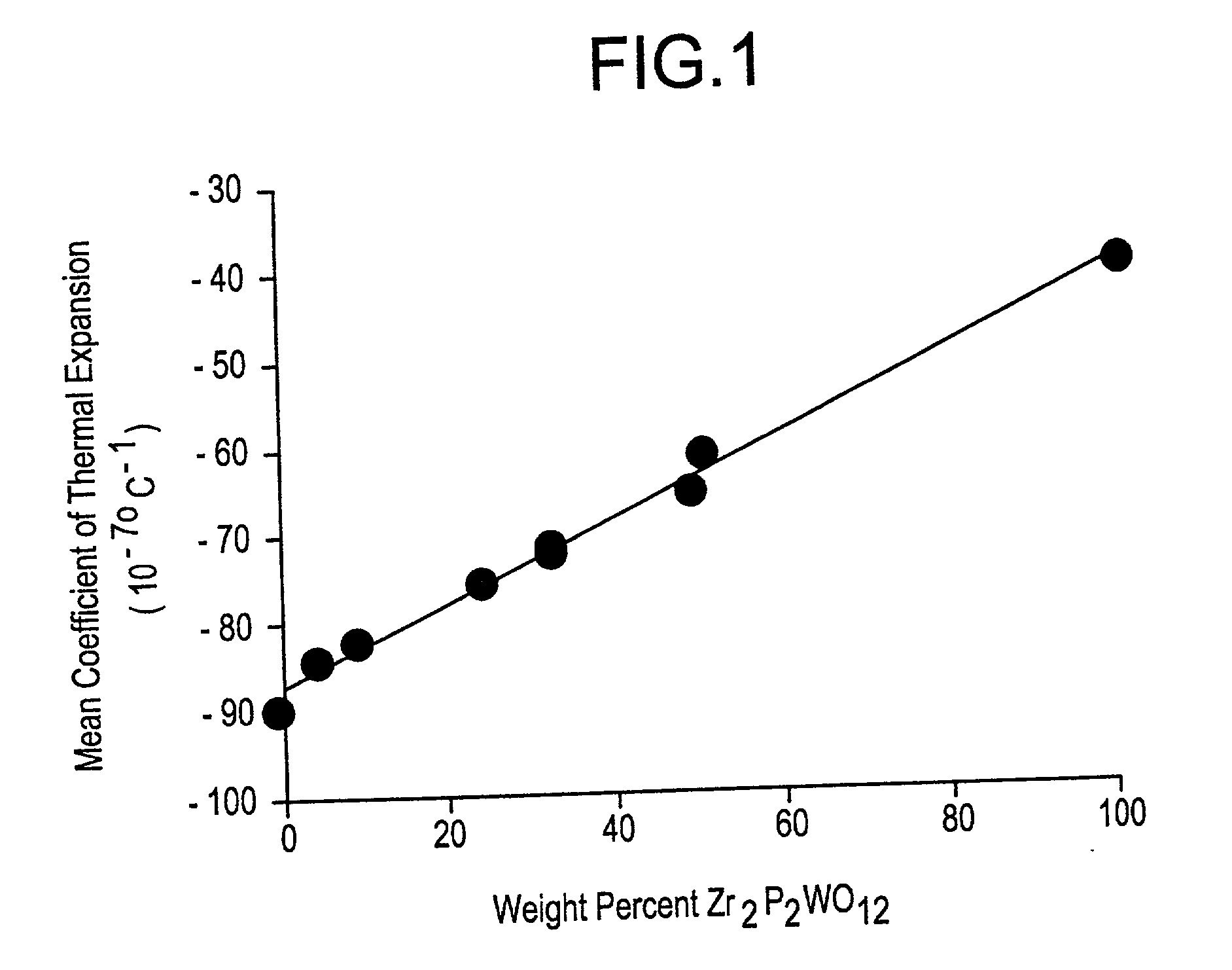
[0057] Powder preparation for Examples 19 and 21-28 was conducted in the same manner as Examples 1-18, with the proportions of the starting materials adjusted to yield Zr.sub.2P.sub.2WO.sub.12 and ZrW.sub.2O.sub.8 in the ratios stated in Table 2. In these examples, the weight percentages of Zr.sub.2P.sub.2WO.sub.12 and ZrW.sub.2O.sub.8 are relative to the sum of the weights of the Zr.sub.2P.sub.2WO.sub.12 and ZrW.sub.2O.sub.8 components only. Weight percent of additive is relative to total weight percent of starting material.

2TABLE 2 Experimental data for Zr.sub.2P.sub.2WO.sub.12 ceramics with various amounts of ZrW.sub.2O.sub.8. Heating rate Weight Weightabove Example % % Weight % Sample 900.degree. C. Soak Soak Number Zr.sub.2P.sub.2WO.sub.12 ZrW.sub.2O.sub.8 Additive Additive Geometry (.degree. C. / hr) Temp Time 19 100 0 0.00 none 7.6 cm 200 1150 4 bar 20 50 50 0.00 none 7.6 cm 100 1150 4 bar 21 49 51 0.00 none 7.6 cm 200 1150 4 bar 22 32 68 0.00 none 7.6 cm 100 1150 4 bar 23 32 6...

example 20

[0058] prepared by precipitation from aqueous solutions of ZrOCl.sub.2.8H.sub.2O, NH.sub.4H.sub.2PO.sub.4, and H.sub.2WO.sub.4. According to this method, 79.18 grams of zirconyl chloride (previously assayed to be 2.739.times.10.sup.-3 moles Zr per gram of salt) was dissolved in 161 grams of water to form the first solution. A second solution was formed by dissolving 16.63 grams of ammonium dihydrogen phosphate in 73 grams of water. A third solution was made by dissolving 54.19 grams of tungstic acid in 152 grams of water and 54 grams of 14.8 N ammonium hydroxide solution, and heating to 95.degree. C. The tungsten and phosphate solutions were mixed together and then added to the zirconium solution. More ammonium hydroxide was added to the mixture to deflocculate the suspension. The slurry was stirred and heated to 85.degree. C. until dry. The solid was then calcined at 900.degree. C. for 4 hours and subsequently crushed and vibratory milled in isopropanol for 14 hours with zirconia m...

examples 29 to 88

[0062] Powder preparation for Examples 29 to 88 was conducted in the same manner as Examples 1-18, with the proportions of the starting materials adjusted to yield Zr.sub.2P.sub.2WO.sub.12 and ZrW.sub.2O.sub.8 in the ratios stated in Table 2, with the following exceptions: Example 68 was prepared using ZrO.sub.2, WO.sub.3, and a ZrP.sub.2O.sub.7 powder prepared by calcination of acid zirconium phosphate at 1050.degree. C. for 4 hours, and Examples 69 and 73-78 were prepared from ZrO.sub.2, WO.sub.3, and pre-reacted Zr.sub.2P.sub.2WO.sub.12. The pre-reacted Zr.sub.2P.sub.2WO.sub.12 was formed by dry ball milling a mixture of ZrO.sub.2, WO.sub.3 and acid zirconium phosphate in the appropriate ratios and calcining the mixture at 1050.degree. C. for 4 hours. Also, the powders for Examples 72 to 78 were milled in water instead of isopropanol. Examples 29 to 88 were formulated to yield ceramics with coefficients of thermal expansion between -65 and -85.times.10.sup.-7.deg-ree. C..sup.-1.

[...


PUM

PropertyMeasurementUnit
temperatureaaaaaaaaaa
melting pointaaaaaaaaaa

Abstract

Negative thermal expansion materials, methods of preparation and uses therefor are disclosed. The materials are useful for negative thermal expansion substrates, such as those used for optical fiber gratings.

Description

[0001] This application claims priority to U.S. application Ser. No. 09 / 305763, filed on May 5, 1999, which claims priority to Provisional U.S. Application No. 60 / 086,053, filed on May 19, 1998, the contents of which are herein incorporated by reference.[0002] The invention pertains to negative thermal expansion materials, devices made therefrom, and methods of making the materials. More particularly, the present invention concerns compositions including zirconium phosphate tungstates, which can be used to make substrates for athermalized optical fiber reflective grating devices.[0003] Negative thermal expansion (contraction with increasing temperature) is an unusual and potentially useful property for a solid material, and very few crystalline materials possess strongly negative expansions over an extended temperature range. Materials that exhibit a negative expansion due to extensive microcracking, by virtue of a negative coefficient of thermal expansion ("CTE") along at least one...

Claims


Application Information

Patent Timeline
Patent Type & Authority Applications(United States)
IPC IPC(8): C04B35/01C04B35/00C04B35/48C04B35/495G02B6/00G02B6/02G02B6/12
CPCC04B35/01C04B35/495G02B6/0218G02B6/12
Inventor MERKEL, GREGORY A.
Owner CORNING INC
Why Eureka
Try Eureka