[0020]The biosensor cell of the present invention provides several advantages, one of which is that low levels of hybridization (if nucleic acids are used as capture and target molecules) or of
complex formation (if at least one of the two binding partners is not a
nucleic acid, for example, if a
nucleic acid binding or a
hapten binding
antibody is used as capture molecule) can be detected, due to the fact that the structure of the biosensor makes it
highly sensitive to small leakage current caused by small amounts of hybridization of target molecules conjugated with
electrically conductive particles. Another
advantage of the invention is that when the biosensor cell of the present invention is implemented in the form of a
biosensor array, it is capable of making thousands of independent measurements across an entire
biosensor array, can therefore provide statistically significant readings as to whether hybridization has occurred.
[0021]In the context of the present application, the term “capture molecule” generally refers to any molecule that has selective affinity towards a “target molecule”. The term “capture molecule” is used interchangeably with the term “probe”, or probe molecule, while the term “target molecule” is used interchangeably with the term “
analyte” or “sample
biomolecule”. The term “capture molecule” encompasses, for example, nucleic acids, proteins, carbohydrates, low weight molecular compounds and any other molecule, that exhibits affinity for a target molecule and can form a complex with the target molecule of interest. Examples of nucleic acids include deoxyribonucleic acid (DNA), ribonucleic acid (
RNA) or
peptide nucleic acid (PNA) molecules. Examples of proteins that can be used as capture molecules include antibodies and fragments thereof, artificial proteins with
antibody-like properties (meaning they can be generated to have binding affinity towards a given target) such as, but not limited to,
lipocalin muteins as described in Beste et al., Proc. Natl. Acad. Sci. USA 96, 1999, 1898-1903, WO 99 / 16873, WO 00 / 75308, WO 03 / 029471, WO 03 / 029462, WO 03 / 029463, WO 2005 / 019254, WO 2005 / 019255 or WO 2005 / 019256, so-called glubodies (see WO 96 / 23879), proteins based on the
ankyrin scaffold (Hryniewicz-Jankowska A et al., Folia Histochem. Cytobiol. 40, 2002, 239-249) or crystalline
scaffold (WO 01 / 04144,). Other examples of proteins that can be used as capture molecules are
protein A,
avidin, or
streptavidin that are commonly used in
biochemistry in order to immobilize a target molecule of interest via their specific binding to Fc chains (
protein A) or
biotin or
biotin analogues (
avidin,
streptavidin). Examples for low weight molecular compounds that are suitable capture molecules are haptens or molecules such as
biotin or
digoxigenin that are commonly as
label due their specific binding to
streptavidin and
digoxigenin binding antibodies, respectively. Examples of carbohydrates that can be used as capture molecules are lectins. Corresponding target molecules or analytes may be obtained from living organisms as well as molecules obtained from environmental samples. Examples of target molecules include macromolecular biomolecules such as nucleic acids (e.g. a
target gene or mRNA transcript), proteins, carbohydrates, peptides, metabolites, other small molecules (for example, chemical pollutants or toxins such as dioxins or DDT) as well as macromolecular biological structures such as entire cells or organisms that carry on their surface target molecules that are bound by the used capture molecule. Other suitable combinations of capture molecules and target molecules that are within the scope of the present invention are, for instance, the examples comprising the method disclosed in PCT applications WO 99 / 57550 A1, Nature Vol. 391 (1998) 775, Nature Vol. 403 (2000) 635. In order to facilitate
complex formation, the target molecule can, for example, also be labelled with a small molecular compound such as biotin or
digoxigenin that acts as a ligand for the above-mentioned proteins.
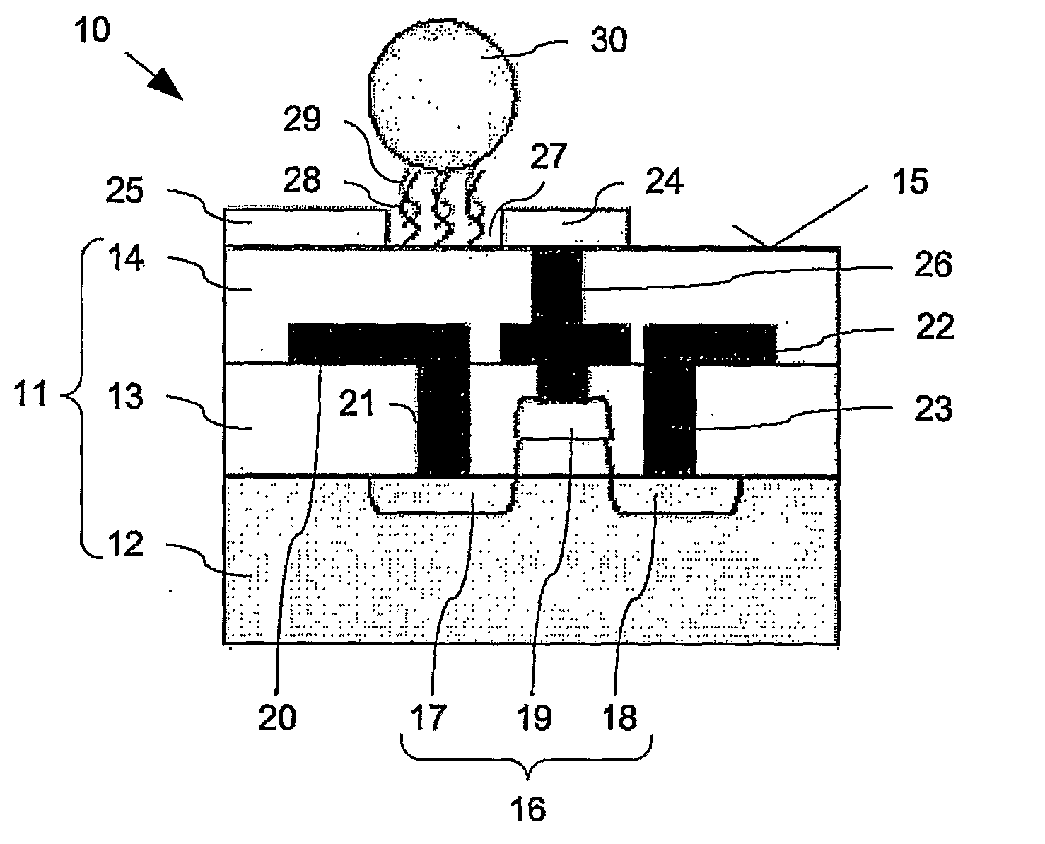
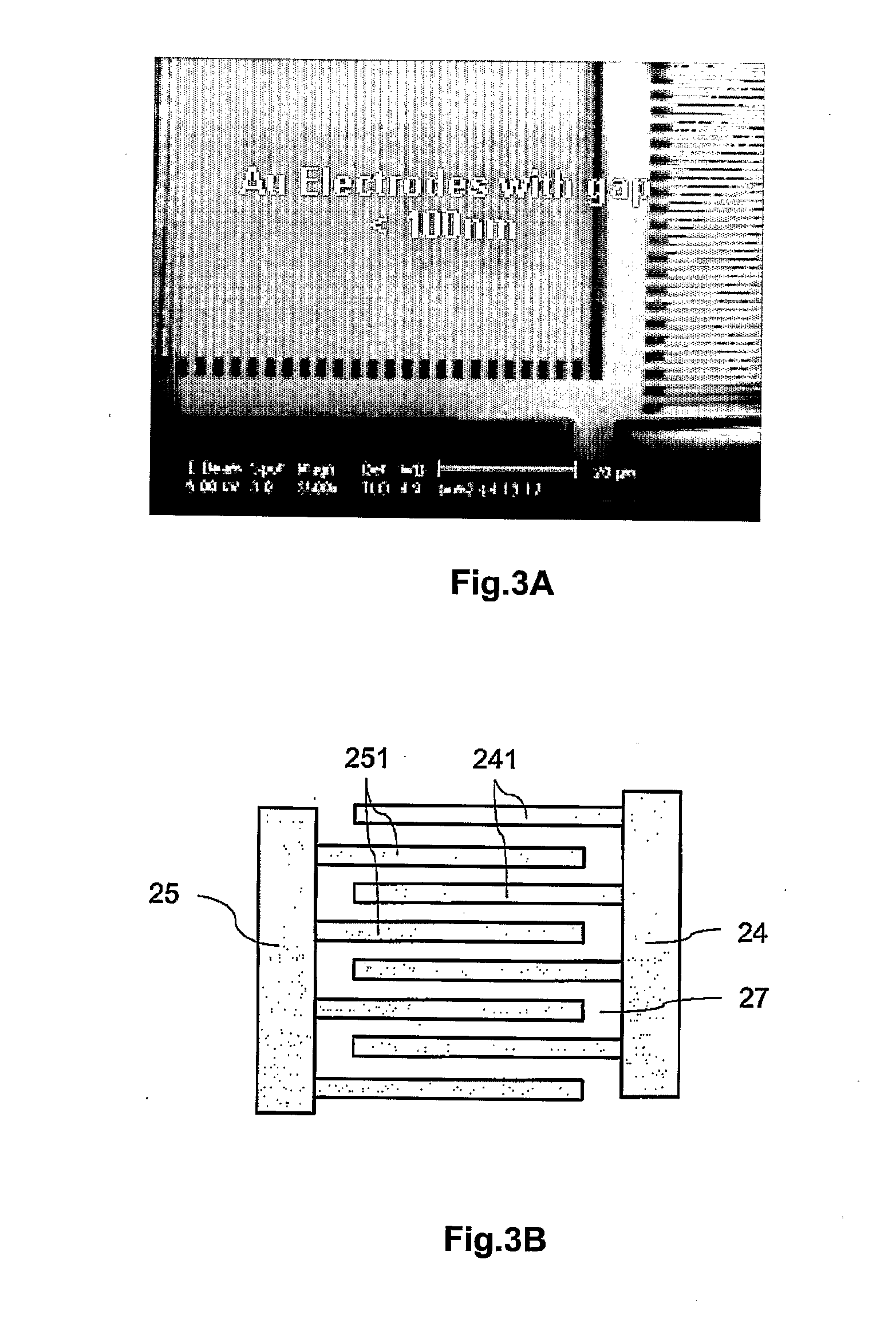
[0022]The sensing zone on which capture molecules are arranged refers to any region
proximate to the first and the second sensing electrodes on which detection of binding events are detected. Arranged within the sensing zone is a first sensing electrode, a second sensing electrode and a gap separating the electrodes. The target molecule to be analysed may be modified by attachment to an
electrically conductive particle. The sensing region is arranged / selected such that when these target molecules are bound to capture molecules within the sensing zone, the
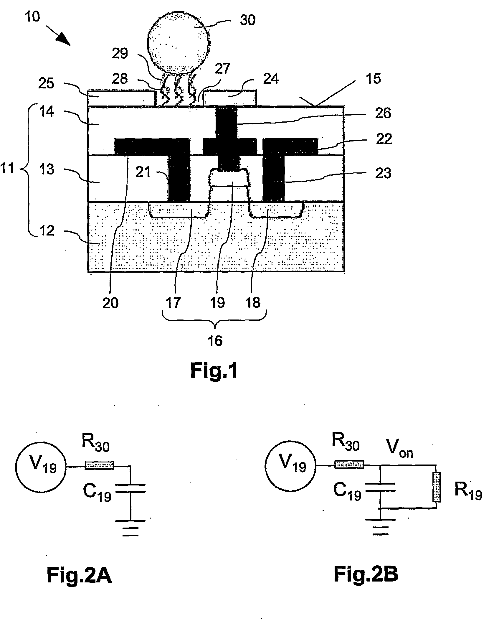
electrically conductive particles either comes into direct contact with both sensing electrodes or at least provides a pathway for current flow between the two sensing electrodes. When current (hereinafter “leakage current”) flows between the two electrodes, the gate electrode of the
field effect transistor (FET) is charged. This charged state switches on the FET, thus providing a
signal indicating positive detection. In this manner, the electrical
conductivity between the sensing electrodes is measurably altered when target molecules are bound. This change can be detected by the
field effect transistor, and thus allows detection of binding events.
[0023]In order for the leakage current between the sensing electrodes to be readily detected via the
field effect transistor, the
diameter of the electrically conductive particle is preferably chosen to be comparable to the size of the gap between the first sensing electrode and the second sensing electrode, and in particular, between about 10 nm to about 150 nm. In some embodiments, the
diameter of the electrically conductively particle is smaller than the width of the gap. If the electrical conductively particle is to have a smaller size than gap, they may be coated with other
metallic materials such as silver or gold, etc., to augment or enlarge the size of the electrically conductive particle to short the sensing electrodes.
[0024]Target molecules can be located at any position within the sensing region, as long as the electrically conductive particles attached to them are able to connect the first sensing electrode to the second sensing electrode. In one embodiment, capture molecules are immobilized in the gap which separates the two sensing electrodes. Alternatively, or concurrently, the capture molecules are immobilised on a surface of either one or both of the first and / or the second sensing electrodes.
[0025]In an alternative embodiment, the target molecule is not modified by the attachment of an electrically conductive particle. After such a target molecule is bound to the capture molecules located within the sensing zone, any
reagent that can enhance the
conductivity of the target molecule is added. Such a
reagent may comprise any
metal ion which can be bound to the target molecule, and which can subsequently be reduced to elemental
metal in order that an
electrical current flows between the sensing electrodes, and the current flow is detected by the
field effect transistor. One example of such a
reagent comprises silver ions which can be utilised in a silver enhancement process described in Braun et al. (supra).

