Organic-Inorganic Complexes Containing a Luminescent Rare earth-Metal Nanocluster and an Antenna Ligand, Luminescent Articles, and Methods of Making Luminescent Compositions

a rare earth-metal nanocluster and organic-inorganic complex technology, applied in the field of organic-inorganic complexes, can solve the problems of res not being used successfully, used in the practical field, and reabsorption of luminescence, and achieve the effect of increasing the luminescence of nps

Inactive Publication Date: 2011-09-29
BATTELLE JAPAN CORP
View PDF7 Cites 21 Cited by
  • Summary
  • Abstract
  • Description
  • Claims
  • Application Information

AI Technical Summary

Benefits of technology

[0016]Charbonnière et al., in “Highly luminescent water-soluble lanthanide nanoparticles through surface coating sensitization,”New J. Chem., 2008, describe the reaction of water-soluble La0.95Eu0.05F3.AEP (AEP=aminoethylphosphate) nanoparticles (NPs) with 6-carboxy-5′ methyl-2,2′-bipyridine (bipyCOO−) in water, resulting in an increase of more than two orders of magnitude of the europium centered emission upon excitation at 305 nm. The nanoparticles were about 200 nm in diameter. Nanoparticles coated by the bipyCOO− ligands were prepared by surface ligand exchange in water, isolated and characterized by infrared spectroscopy, transmission electron microscopy, energy dispersion X-ray analysis and dynamic light

Problems solved by technology

However, they have several drawbacks which have prevented them from being used for practical field uses, including (1) degradation due to UV exposure, and (2) the reabsorption of the luminescence due to their overlapping absorption and emission bands.
Nevertheless, REs have not yet been used successfully for the luminescent solar concentrators and spectral converters because of the low solubility of rare earth materials in most organic matrices, and low absorptivity, which results in low external quantum efficiency.
However, the minimum particle diameter of such a powder is several μm at the smallest, which is too large to suppress scattering loss due to Rayleigh scattering.
This causes a fatal problem for luminescent transparent component used in solar cell modules.
One problem associated with rare earth-doped optoelectronic materials is that the concentration of rare earth ions cannot be increased beyond a low threshold due to concentration quenching effects.
The narrow absorption band of rare earth phosphors is unsuitable for efficient use in such devices.
The efficiency of abso

Method used


Image

  • Organic-Inorganic Complexes Containing a Luminescent Rare earth-Metal Nanocluster and an Antenna Ligand, Luminescent Articles, and Methods of Making Luminescent Compositions
  • Organic-Inorganic Complexes Containing a Luminescent Rare earth-Metal Nanocluster and an Antenna Ligand, Luminescent Articles, and Methods of Making Luminescent Compositions
  • Organic-Inorganic Complexes Containing a Luminescent Rare earth-Metal Nanocluster and an Antenna Ligand, Luminescent Articles, and Methods of Making Luminescent Compositions

Examples


examples

Dependence of Michler's Ketone (MK) / RE-M Nanocluster Ratio on the Sensitization

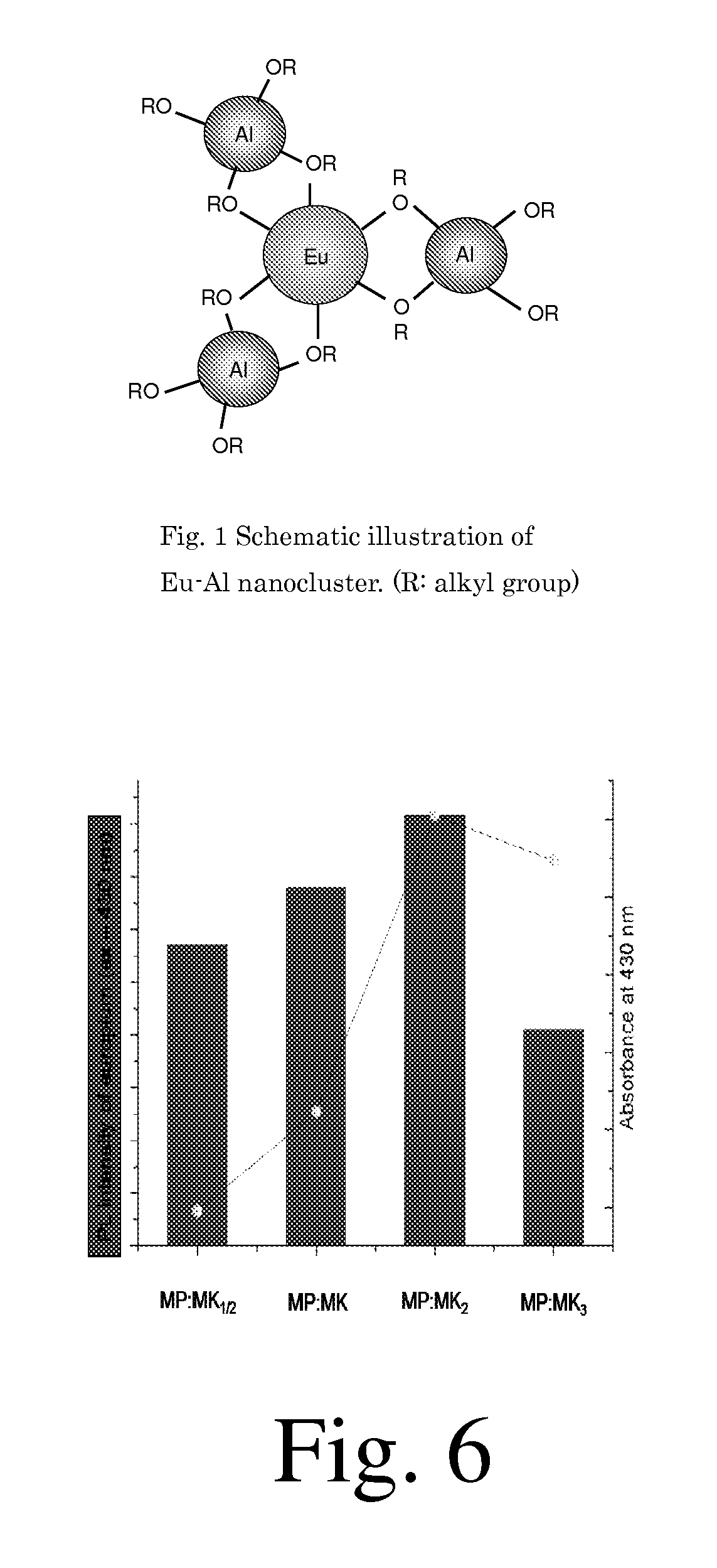
[0090]The molar ratio of MK / Eu—Al nanocluster was varied; 0.5, 1, 2, and 3. Methylmethacrylate (MMA) doped with MK / Eu—Al was coated onto a silica (SiO2) substrate. The film thickness was about 400 Å. The photoluminescence spectra were obtained by exciting the film with monochromatic light at a wavelength of 430 nm. The result (see FIG. 6) revealed that the photoluminescent intensity is maximized when the MK / Eu—Al nanocluster ratio is about 2; with intensity increasing in the order 3<0.5<1<2. At the ratio of 3, the photoluminescent intensity drops significantly. It is therefore favorable to control the MK / Eu—Al nanocluster within ratios of 0.5 to less than 3 and, more preferably in the range of 1.0 to 2.5. This result is generalized to desirable ratio of antenna ligand to RE atom in a nanocluster.

Solar Cell Efficiency Measurement

embodiment 1

[0093]A mixture of MMA, Eu—Al nanocluster (5% by weight) and DEAP (0.5% by weight) (Eu—Al / MMA) was coated onto single-crystalline Si (c-Si) solar cells by spin-coating at a rotation speed of 1000 rpm and polymerized as above. As a result, the change rates of the solar cell efficiency after coating compared with before coating ranges from 0% to +14%. When comparing with the control, this indicates that the solar cell efficiency of c-Si solar cell was enhanced.

Solar Cell Efficiency Measurement

embodiment 2

[0094]A mixture of MMA, Eu—Al nanoclusters (5% by weight), MK (molar equivalent to Eu—Al nanocluster) and DEAP (0.5% by weight) was coated onto single-crystalline Si (c-Si) solar cells by spin-coating at a rotation speed of 1000 rpm and polymerized. As a result, the change rates of the solar cell efficiency after coating compared with before coating ranges from 0% to +19%. When comparing with the previous examples, it is clear that the solar cell efficiency of c-Si solar cell was enhanced and that the enhancement rate was significantly larger than Eu—Al nanocluster alone.

Spectral Conversion

[0095]We used the Eu—Al nanocluster [Eu—Al3](OAc)3(O-isoBu)9 as an example of the RE-M nanocluster and this nanocluster was dispersed at 5% by weight in a methyl methacrylate (MMA) solution. The procedures for the synthesis of Eu—Al nanocluster and its doping into MMA (Eu—Al / MMA) are described elsewhere. See for example H. Mataki and T. Fukui, Proc. of 2005 5th IEEE Conference on Nanotechnology (N...


PUM

PropertyMeasurementUnit
Sizeaaaaaaaaaa
Sizeaaaaaaaaaa
Sizeaaaaaaaaaa

Abstract

Luminescent compositions are described comprising lanthanide-containing nanoclusters comprising lanthanide atoms bonded to at least one semimetal or transition metal via an oxygen or sulfur atom. Novel compositions include an antenna ligand complexed with the nanoclusters. The rare earth-metal nanoclusters are in the size range of 1 to 100 nm. Articles, such as solar cells, are described in which the nanoclusters (with or without antenna ligands) are dispersed in a polymer matrix. Novel methods of making luminescent films are also described.

Description

RELATED APPLICATIONS[0001]This application is a national stage filing of PCT / US2009 / 054371 and claims priority to U.S. Provisional Patent Application Ser. Nos. 61 / 090,191 filed 19 Aug. 2008, 61 / 145,515 filed 16 Jan. 2009, and 61 / 184,197 filed 4 Jun. 2009.INTRODUCTION[0002]The invention relates to novel luminescent compositions, methods of making luminescent articles, devices containing luminescent material, and methods of using luminescent articles. The invention also relates to a solar cell comprising a luminescent transparent component, which is placed in front of or in the back of a solar cell so that the solar cell detects either the luminescent light or the sunlight whose spectrum is modified.[0003]There are two types of luminescent materials that have long been investigated: luminescent organic dyes, and rare earths materials.[0004]Luminescent organic dyes have been the most commonly studied for luminescent concentrators and spectral converters. See Reisfeld, et al., U.S. Pat....

Claims


Application Information

Patent Timeline
IPC IPC(8): H01L31/0216C09K11/02C08F230/04C09K11/06B82Y30/00B82Y40/00C07F5/06H01L31/055
CPCC09K11/06Y10T428/2982C09K2211/182C09K2211/186H01L31/055Y02E10/52H01L31/0547C09K11/7728C09K11/771C09K11/025C09K11/7734C09K11/7714C09K11/7713C09K11/7701C09K11/7707C09K11/7706C09K11/7709C09K11/7708C09K2211/1007
Inventor MATAKI, HIROSHIRISSER, STEVEN M.MCGINNISS, VINCENTNIPPA, DAVID W.BURROWS, PAUL EDWARDSPADMAPERUMA, ASANGA B.KUNDU, SAMBHU N.
Owner BATTELLE JAPAN CORP
Why Eureka
Try Eureka