Method of mineral fuel beneficiation with subsequent delivery to the consumer by pipeline transportation

a mineral fuel and pipeline transportation technology, applied in the direction of fuels, transportation and packaging, light and heating equipment, etc., can solve the problems of losing consumer properties, calorific value, and inability to store out of doors for as long

Inactive Publication Date: 2013-04-25
ENKHBOLD CHULUUN
View PDF5 Cites 7 Cited by
  • Summary
  • Abstract
  • Description
  • Claims
  • Application Information

AI Technical Summary

Benefits of technology

[0033]FIG. 1 illustrates a flow diagram of Solid Fuel Beneficiation and Transportation to Thermoelectric Power Stations
[0034]FIG. 2 illustrates a flow diagram of Cryo-Gravitational Mineral Dressing
[0035]FIG. 3 illustrates a flow diagram of Coal Delivery to a Heat Power Plant for C

Problems solved by technology

However, coal, in contrast to quartz sand, is not a chemically inert material and it cannot be stored out of doors as long as is wished without losing its consumer properties.
By this reason, huge piles of coal become the source of regularly occurring fires, to say nothing of the fact that even without combustion, the irreversible endogenous oxidation processes of coaly substance taking place in such coal piles decrease substantially the calorific value of coal, which results in the increase of solid fuel demand and consequently, to a significant drop in power production efficiency.
The delivery of fuel for combustion from such ‘deposits’, especially in winter, when coal loses its flowability and fuses into a frozen monolith, becomes no less, and sometimes even more cumbersome than mining from natural deposits, where the coal brittleness remains unchanged over the entire course of coal field development.
Apart from the irreversible loss of a substantial fraction of coal consumer value, the intermediate storage and railroad transportation of coal together with numerous handling operations throughout the whole process, from the mine coalface to the power plant boiler furnace, result in significant mechanical losses of flowable material due to intense dusting.
In fact, only coal blowing by wind during railroad transportation results in losses of 2 to 5 tons of coal per car, depending on coal coarseness, weather, and train speed.
Besides huge economical losses, with regard for the fact that annual world coal production is measured by billions of tons, the coal dust ingress into environment represents a serious ecological and pressing sanitary problem, in particular, for communities located in the immediate vicinity of coal dusting sites.
However, the magnetite density (5.2-5.5 g/cm3) exceeds that of coal (1.3-1.5 g/cm3) by several times. By this reason, this artificial heavy medium, aqueous magnetite suspension, which is unstable under stationary conditions, cannot be used for the separation of coal from waste rock under these conditions.
However the stable maintenance of magnetite in suspended state by constant agitation requires continuous power consumption.
Besides, the intense agitation mode maintained in various separation devices prevents from clear separation of particles with close densities representing aggregates of coal with waste rock.
This results in inevitable contamination of coal concentrate with mineral impurities, as well as coaly substance carryover to dump together with dressing tails; this is especially true for coarse fractions of material being processed.
However, the density of water is too small to provide the efficient lamination of minerals constituting the raw material.
However, the flotation beneficiation methods are by an order of magnitude more expensive than the gravity methods.
Besides, stockpiling of coal flo

Method used


Image

  • Method of mineral fuel beneficiation with subsequent delivery to the consumer by pipeline transportation
  • Method of mineral fuel beneficiation with subsequent delivery to the consumer by pipeline transportation
  • Method of mineral fuel beneficiation with subsequent delivery to the consumer by pipeline transportation

Examples


example 1

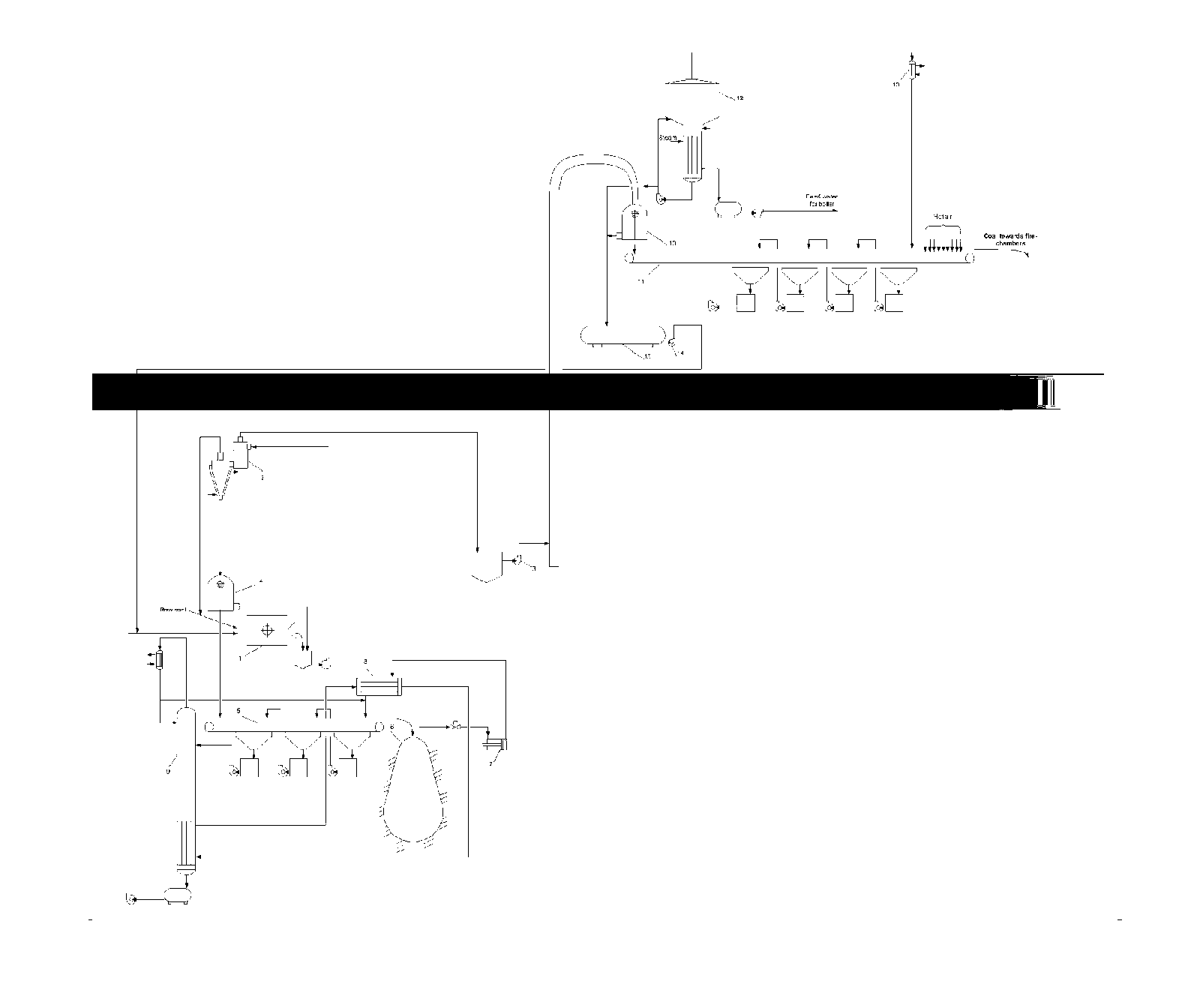
[0058]FIG. 1 shows the flow diagram of underground treatment process of the initial rock portion that requires additional size reduction under deep mining conditions, where the rock remains sufficiently heated by heat of interior the whole year round, irrespective of meteorological conditions, and when the coal produced is intended for a power plant.

[0059]This portion of initial rock separated by screening and requiring additional size reduction to improve waste rock separation is ground in rattler 1 flooded with liquid whose density is intermediate between those of fossil fuel and rock refuse. The rattler operates in closed cycle with three-product heavy-media hydrocyclone 2.

[0060]Liquid represents an aqueous solution of calcium nitrate / zinc chloride mixture having a density of 1.48 g / cm3.

[0061]The beneficiated product, leaving hydrocyclone 2 remains suspended in heavy aqueous medium, which first brings the product to a pitbottom, and then by pump 3 and ground pumping stations (not...

example 2

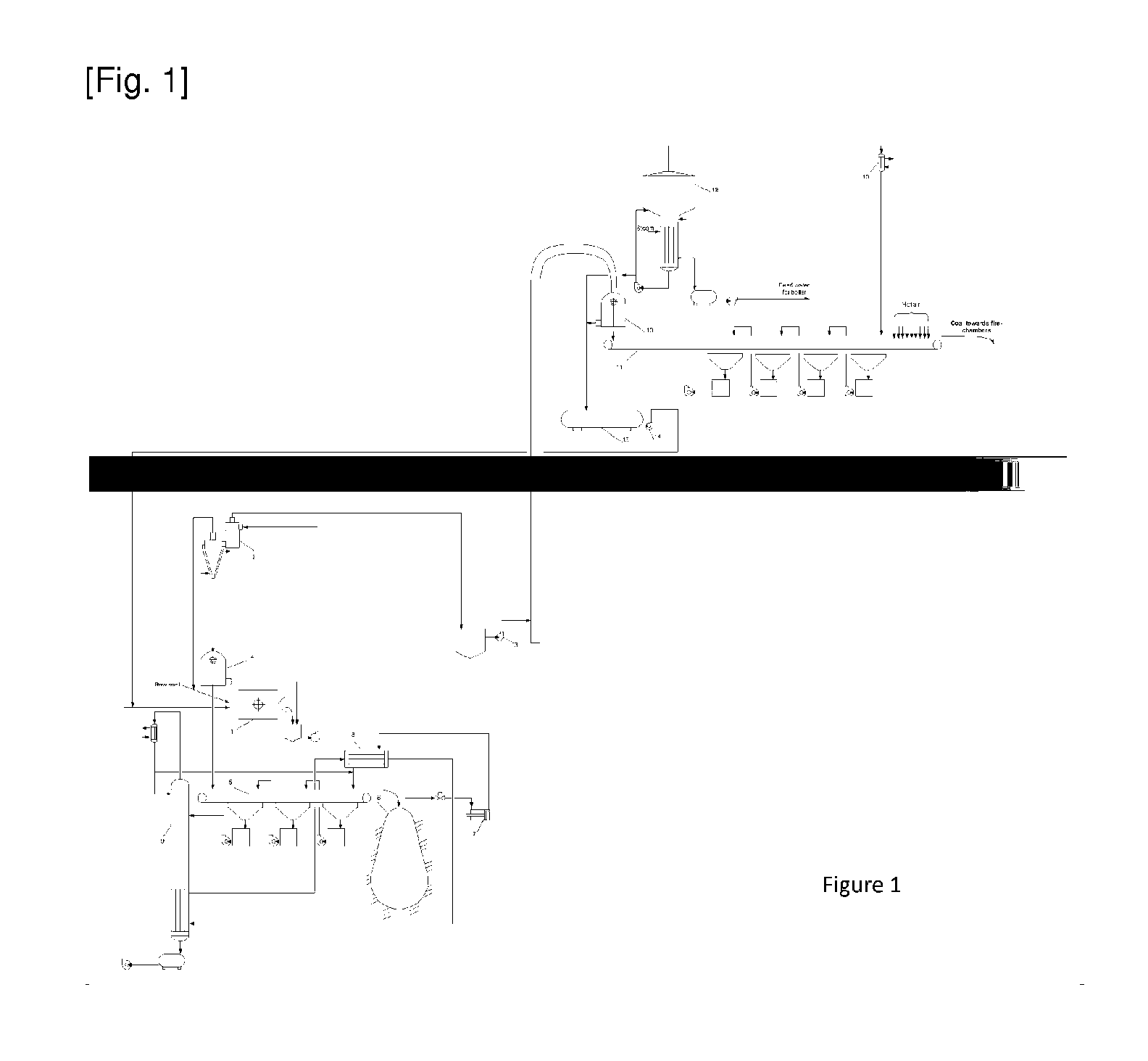
[0073]FIG. 2 shows the flow diagram of underground beneficiation of powder-like mass resisting highly selective dry separation. Treating this part of raw material in aqueous solutions of mineral salts results in the reduction of separation efficiency due to increased effect of water-salt medium rheological characteristics on highly dispersed material, while, a high humidity of paste-like beneficiation products leads to the increase of power consumption associated with the discharge of dry coal and dry final tails.

[0074]In this case, liquid argon, non-aqueous cryogenic liquid with a density intermediate between those of fossil fuel and rock refuse, is used as a separating medium. The boiling point of this liquid is so low that the discharge of dry beneficiation products takes place automatically due to irreversible boiling-up of liquid phase residues due to contact with the environment.

[0075]To this end, initial powder-like run-of-mine coal is fed from bin 1 through gate 2 to recuper...

example 3

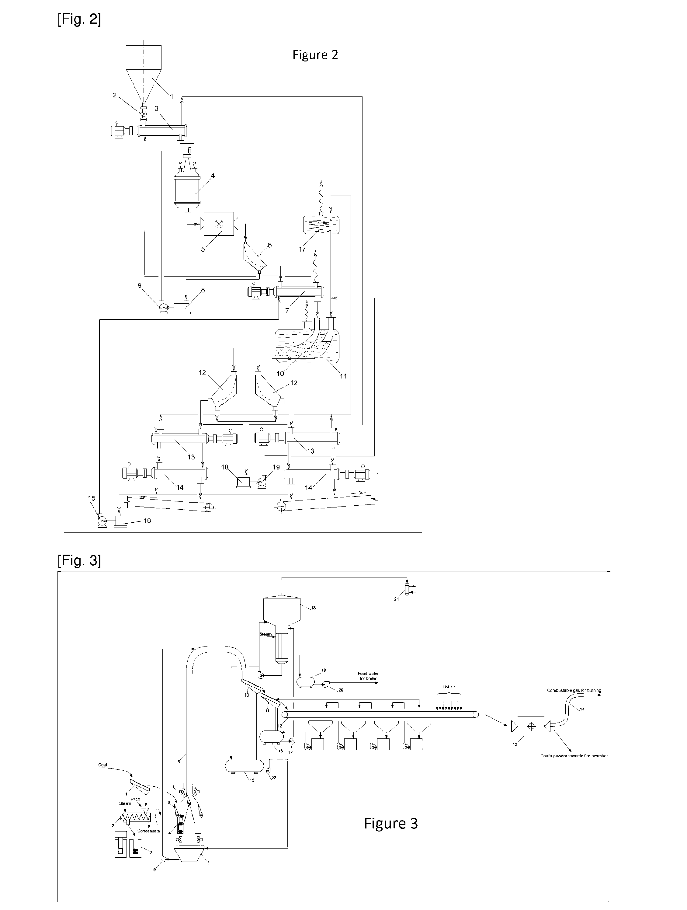
[0086]On FIG. 3 is represented the basic technological scheme of joint delivery lumpy and powdery coal from mine on surface in case the consumer of such firm fuel is the thermal power station.

[0087]Coal delivered in main stream from mining faces to the shaft bottom is classified on separator 1 into lumpy material and fines comprising both fine pieces of coal and all its dusty fractions.

[0088]Coal fines separated from lumps and large pieces are fed by screw feeder 2 equipped with a heat-exchange jacket to press mold 3 for pressing. A moderate amount of pitch is introduced into screw feeder 2 as a binding additive, which strengthens monolithic blocks made from coal fines in the form of cylindrical bodies resembling pistons of hydraulic facilities by their shape. Steam for heating coal mixture with pitch before pressing is fed into its heat-exchange jacket.

[0089]Batches of lumpy coal and coal blocks apiece are alternately arranged in loading chamber 4 of the loading system of transport...


PUM

PropertyMeasurementUnit
Temperatureaaaaaaaaaa
Concentrationaaaaaaaaaa
Densityaaaaaaaaaa

Abstract

A method of mineral fuel beneficiation with subsequent delivery to the consumer by pipeline transportation relates fuel and energy complex and can find application in coal and slate energetics. Invention main objective is security of solid fuel delivery from mine (or an open cut coal mine) in already enriched form, with its subsequent through delivery to the consumer by pipeline on any distances in stream mode, without any intermediate transshipment operations. For this purpose use liquid with set complex physical, sanitary-and-hygienic and ecological properties, simultaneously, in 4 qualities: As environment for grinding material that needed further reduction of size; As separation environment for the subsequent, after reduction of size, deep underground gravitational enrichment of combustible mineral, As motionless filler of the vertical pipeline, for buoyancy in it ready product from mine on terrestrial surface: As carrying medium for final drift of end-product to the consumer by main pipeline. Depending on consumer type of solid fuel, a time of year, and weather conditions in which such, non-polluting, mining-energetic complex functions, there are used various technological approaches as to the general principles of construction of such, non-polluting, beneficiating transport technological process as well as within the limits of separate links of such technological chain, various methods of the regeneration, used many functional liquids which are in the closed contour of circulation between producer of solid fuel and its consumer.

Description

TECHNICAL FIELD[0001]The present invention relates to mining of different kinds of power generating fossils and can be used in coal, shale mining, and other branches of mining industry connected to solid fuel consumers via transportation infrastructure facilities.BACKGROUND ART[0002]The traditional method of providing various consumers with coal or another solid mineral fuel is well known. To this end, the run-of-mine coal is delivered to the earth surface storage by skip hoists and concentrated at a coal-concentrating plant. Then, thus produced high-quality solid fuel is shipped from the finished product storage to the consumer via railway transport.[0003]Cleaned coal arrived to the destination point is discharged from cars, piled up at open areas, and then delivered for its direct application (see, e.g., Golitsyn M. V., M. B Golitsyn A. M. Everything About Coal. Moscow, Nauka Publishers, 1989.-192 pp.)[0004]The above production string includes several storage operations, which is ...

Claims


Application Information

Patent Timeline
IPC IPC(8): E21C41/16B03B9/00
CPCB03B9/005C10L1/326C10L9/00C22B1/00E21F13/002F23K3/02B03B9/00E21C41/16F23K1/02
Inventor ENKHBOLD, CHULUUNALEXANDER, BRODT
Owner ENKHBOLD CHULUUN
Why Eureka
Try Eureka