Doped conductive oxides, and improved electrodes for electrochemical energy storage devices based on this material

a technology of conductive oxides and electrodes, which is applied in the direction of electrical equipment, fuel cells, cell components, etc., can solve the problems of conductive oxides, low energy density of current secondary batteries, and inability to meet the needs of electric vehicles as power supplies and large-scale energy storage areas, etc., to achieve stable three-dimensional structure, good interface, and easy to perform large-scale production

Inactive Publication Date: 2018-06-28
NANTONG VOLTA MATERIALS LTD
View PDF3 Cites 3 Cited by
  • Summary
  • Abstract
  • Description
  • Claims
  • Application Information

AI Technical Summary

Benefits of technology

[0037]The technical effect of the invention is that:
[0038]1) The materials synthesis process is simple. Industrial set-ups have been widely used in the synthesis of a large number of different chemical products; therefore it is easy to perform large-scale production;
[0039]2) The obtained doped oxide has a stable three-dimensional structure, which is beneficial to the formation of a good interface with the positive lead paste during the curing process. The structure of the material does not change during the operation process, suppresses the positive sulfation and provides stable conductive network, thus improving the cycle life;
[0040]3) The obtained doped oxide is favorable for the interface between the negative grid and the negative electrode paste to form a good interface during the cur...

Problems solved by technology

By considering environmental effect (for example, high toxicity of cadmium in nickel-cadmium batteries), cycle life (short lead-acid battery life), cost (high price of rare earth metals), and reliability and safety (for example, safety of lithium-ion battery is poor because their electrolytes are based on organic solvents), the current secondary batteries are neither suitable for electric vehicles as their power supply and nor for large-scale energy storage areas.
Compared to batteries, supercapacitors can provide higher power density and ultra-long cycle life, but the energy density of such devices is too low to be suitable for large-scale energy storage.
In aqueous electrolyte based energy storage system systems, most of the conductive oxides are only stable in some neutral or alkaline electrolytes but unstable in acid electrolytes.
Particularly, in recent years people have been using porous carbon materials to replace the entire or partial of negative electrode material (lead) in the traditional lead acid batteries (CN101563741B, U.S. Pat. No. 7,998,616B2, CN200910183503, KR1020060084441A), which can effectively suppresses the sulfation of the negative electrode in the incomplete charging state, resulting in a significant increase in power and cycle life of the lead acid battery, but these methods reduce the energy density of lead-acid batteries.
However, the overpotential of hydrogen evolution from this tungsten oxide is only slightly higher than the lead negative (˜50 mV), which to some extent limits the working potential of the battery, capacity and cycle performance.
Although these strategies have effectively improved the performance of certain aspects of lead-acid batteries, in general, so far, manufacturing lead acid batteries with sufficiently high power and long enough cycle life (100% DOD cycles>1000 times), is still limited by the activity and stability of the positive and negative electrode materials, including: 1) positive (lead dioxide) active material utilization is low and the resulting positive softening, thermal runaway and water loss; 2) negative active material (lead) suffers from poor high current acceptance capability, sulfation, low cycle life and too much hydrogen evolution.
Generally, the utilization rate of the positive electrode active material of lead-acid battery is about 38%, which is mainly due to the formation of dense insulating PbSO4 after discharge of PbO2, which causes the pores inside the plate to block and prevent the electrolyte diffusion from the surface to the inside, and the lead oxide isolated by the PbSO4 ...

Method used


Image

  • Doped conductive oxides, and improved electrodes for electrochemical energy storage devices based on this material
  • Doped conductive oxides, and improved electrodes for electrochemical energy storage devices based on this material
  • Doped conductive oxides, and improved electrodes for electrochemical energy storage devices based on this material

Examples


example 2

on of Tin-Doped Tungsten Oxide

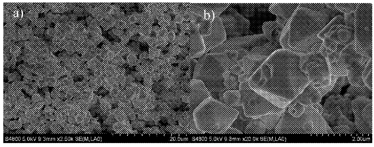
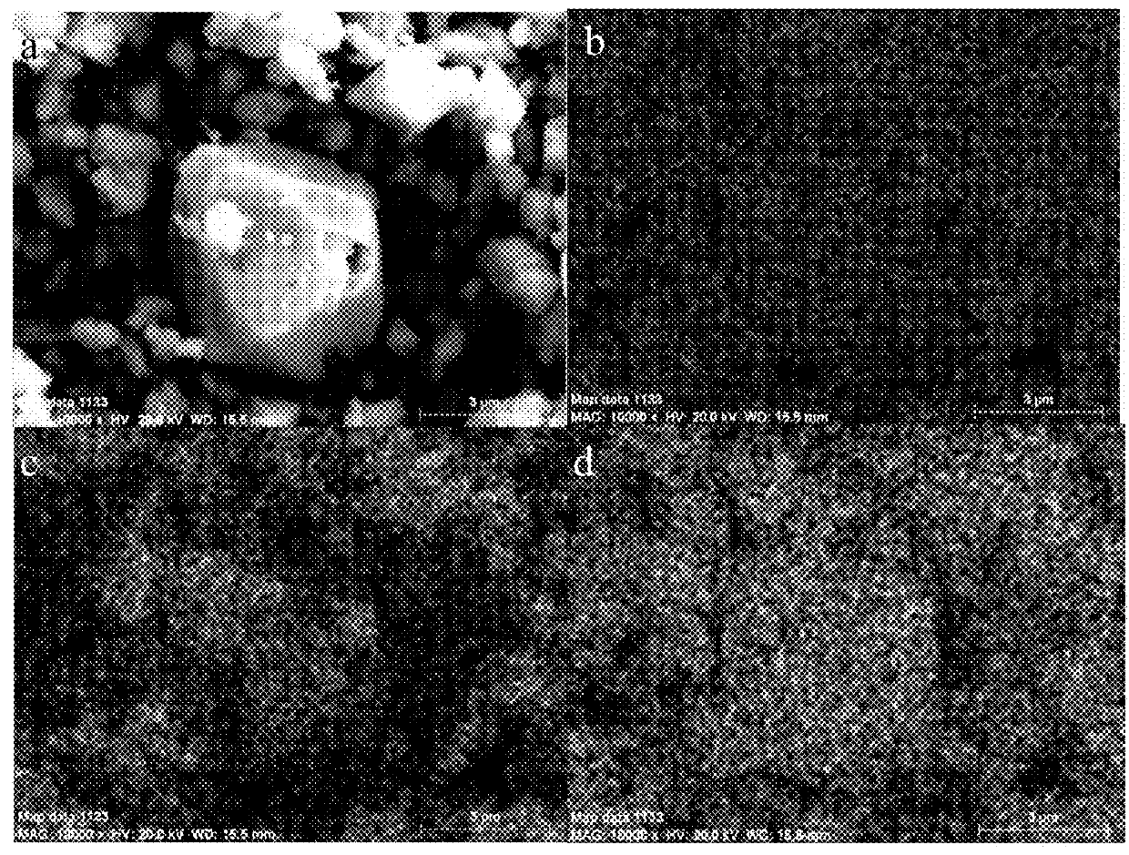
[0070]Using the preparation method of Example 1, the oxide product obtained as described above was mixed with the dopant element precursor, and in the present example, tin powder is blended with oxide powder at a molar ratio of 1:1 in water. The mixture is stirred at a temperature of 100° C. until it is dried and then is passed through an atmosphere sintering furnace at 500-700° C. under nitrogen or a forming gas (N2 / H2) for 5 hours to produce an intermediate doped oxide. The typical morphology is given in FIG. 16b which shows that the obtained oxide is a powder. And the product SnxWO3 is finally formed after sintering in muffle furnace at 300 degrees Celsius for 1-20 hours. The typical morphology of the product SnWO3 shown in FIG. 2, and the particle size is about 5 μm long and the diameter is about 800 nm˜1 μm.

[0071]The properties of the tungsten oxide obtained by Examples 1 and 2 will be described below with reference to the accompanying drawings.

[00...

example 3

on and Electrochemical Properties Characterization of Tungsten Oxide Electrodes

[0077]The tungsten oxide (AxWO3) or molybdenum oxide (AxMoO3) obtained in Example 1-2 is mixed with a conductive agent, a binder and a dispersion solvent in a specific ratio (mass ratio: 94:3:3), wherein the conductive agent, binder and disperse solvent can be selected from common types of conductive agents, binders, and dispersing solvents in the field of electrochemistry. After these components are homogeneously mixed, an electrode slurry (paste) is obtained, applied to the current collector, and dried to form an electrode. The obtained electrode is paired with a lead oxide electrode in a conventional manner, separated by a separator, and an acidic electrolyte is added to form a single cell and subjected to electrochemical test. The results are as follows:

[0078]FIG. 4 shows the comparison of AC impedance spectra before and after linear scanning of Pb0.5WO3 and SnWO3 electrodes obtained by Example 3 and ...

example 4

on of Positive Electrode Plate of Lead-Acid Battery

[0083]The doped tungsten oxide material with was added as an additive to the positive electrode paste at different ratios. The electrode plate is prepared according to the formulation of the positive electrode of the lead acid battery shown in Table 2. The specific parameters for curing and chemical formation are shown in Table 2 and Table 3. Finally, the plate is dried after the formation process. The lead-acid battery is assembled, injected with sulfuric acid electrolyte and sealed using traditional lead-acid battery fabrication process. The battery is tested after setting for 24 hours. The specific results are as follows:

TABLE 2Recipe for lead-acid battery cathode preparationElectrode componentAmountLead powder (75%100kgoxidation)Sulfuric acid5.8L(1.4 g / cm3)De-ionized water12~13Lfiber (1.38 g / cm3)100gMxWO3 or MxMoO3(0-20 wt % in the final pastes / electrode)Density of lead paste4.2g / cm3

TABLE 3Curing parameters for lead-acid battery...


PUM


Abstract

The object of the present invention is to provide a class of novel highly conductive doped oxides and their use as an electrode plate additive for batteries. With tungsten oxide or molybdenum oxide as the precursor, the controllable metal doping leads to the formation of highly conductive oxide materials with high hydrogen evolution and high oxygen evolution potential, and can be stable in the sulfuric acid solution. This material can be used as additive materials for the battery positive and negative electrodes and can effectively reduce the electrode internal resistance, improve the utilization efficiency of active materials, increase charge and discharge rate performance, stabilize the electrode structure and improve cycling life.

Description

TECHNICAL FIELD[0001]The present invention relates to an application having a highly conductive doped oxide material and its application to an electrode of an electrochemical energy storage device.TECHNICAL BACKGROUND[0002]With the depletion of petroleum resources, environmental protection has becoming more and more important. Green energy-related industries will hold great promise as an alternative for petroleum resources. As an important medium for energy storage, batteries will play a decisive role. Their market will grow rapidly with the development of electric vehicles, electric bicycles (electric motorcycles), power tools, solar energy, wind energy and other new renewable energy, as well as power storage, distributed micro-grid and other industries. In order to meet the new market demand, many institutions over the world have invested heavily in the research and development of new energy storage technologies, especially research and development of new energy storage materials....

Claims


Application Information

Patent Timeline
IPC IPC(8): H01M4/485H01M10/08H01M4/14
CPCH01M4/485H01M10/08H01M4/14Y02E60/10Y02E60/50H01M4/62H01M4/8663H01M8/086H01M4/48
Inventor ZHANG, YUHONG
Owner NANTONG VOLTA MATERIALS LTD
Why Eureka
Try Eureka