Process and system for converting carbonaceous feedstocks into energy without greenhouse gas emissions

Inactive Publication Date: 2007-05-22
RAVEN SR INC
View PDF13 Cites 101 Cited by
  • Summary
  • Abstract
  • Description
  • Claims
  • Application Information

AI Technical Summary

Benefits of technology

[0018]The present process avoids the difficult path of attempting to strip and capture the carbon dioxide from stack gases and without attempting to carry out separate chemical reactions of carbon dioxide to attempt to produce useful products. The process and system of the present invention uses unique gasification technology combined with fuel cells to generate electricity at high efficiency. This is accomplished by taking advantage of a very unique property of fuel cells—namely, the two anodic and cathodic reactions are separated by an electronically conducting membrane that keeps the product gases separate. In this way, a combustible feed gas can be fully oxidized in the first half-cell of the fuel cell without being commingled with the final products of the air reduction in the second half-cell electrode, i.e., N2. For example, in coal gasification, synthesis gas is formed consisting predominantly of hydrogen and carbon monoxide. This synthesis gas is fed into the first half-cell, i.e., the anode or negative terminal side, of the fuel cell, such as the solid oxide or molten carbonate types, where it is oxidized to water and carbon dioxide. These gases are not diluted by the typical nitrogen remaining after oxygen reduction in the second or remaining half-cell, i.e., the cathode side or positive terminal, of the fuel side. Nitrogen and combustion gases are commingled when combustion air is used in boilers or furnaces. Thus, in the fuel cell, the synthesis gas (syngas) is oxidized without being combusted with air and without being diluted by other gases. The fuel cell-produced water an

Problems solved by technology

The burning of fossil fuels in boilers to raise high temperature, high-pressure steam that can be used to power turbo-electric generators produces a problem source of carbon dioxide and other greenhouse gases, e.g. methane, ozone and fluorocarbons.
However, to date none of these clean coal programs aim to eliminate the emissions of carbon dioxide and other greenhouse gases.
Efforts to use pure oxygen in power plants and gasification systems to avoid the diluting effects of nitrogen and to achieve higher efficiency suffers from the unacceptable cost of requiring an air separation plant and the problems of excessive temperatures in oxygen-fed combustion turbo-generators.
Today there is worldwi

Method used


Image

  • Process and system for converting carbonaceous feedstocks into energy without greenhouse gas emissions
  • Process and system for converting carbonaceous feedstocks into energy without greenhouse gas emissions
  • Process and system for converting carbonaceous feedstocks into energy without greenhouse gas emissions

Examples


Embodiment Construction

[0034]Preferred Embodiment of Process for Hydrogen Fuel Cell Energy Without Production of Unwanted Greenhouse Gases Using a Kiln.

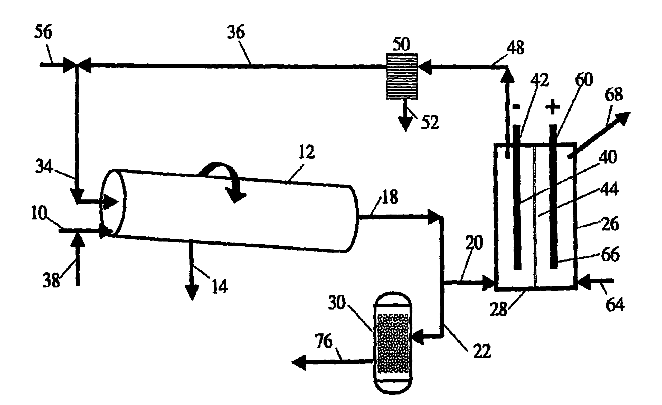
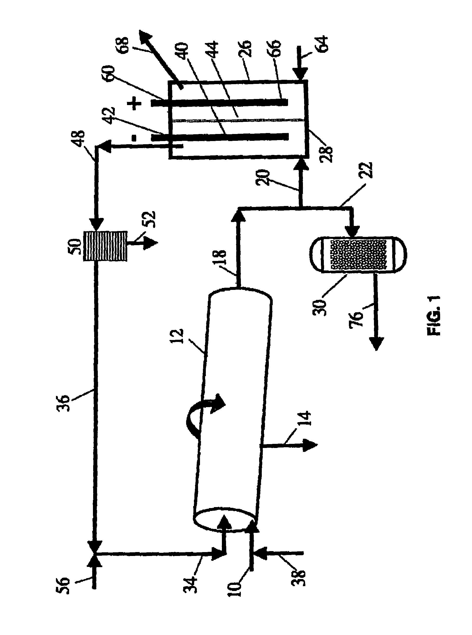
[0035]FIG. 1 illustrates a specific embodiment of the process and system of the present invention in which a carbonaceous waste feed material is passed via inlet line 10 to a non-catalytic high temperature, gas-phase reactor 12 and is converted into synthesis gas at high temperature in the range of about 700° to about 1600° C. (1300-2900° F.). Preferably, a rotary kiln is used as gasifier 12 having outlet 14 to remove the buildup of solids. The syngas produced in gasifier 12 that leaves through outlet line 18 is then split downstream into two flow lines 20 and 22. The syngas in flow line 20 enters fuel cell 26 at port 28. The second syngas stream is passed via flow line 22 to Fischer-Tropsch catalytic reactor 30.

[0036]Preferably gasifier 12 is a slightly inclined horizontal rotary kiln that is heated externally and is called an “indirectly heated rotary ki...


PUM


Abstract

The process and system of the invention converts carbonaceous feedstock such as coal, hydrocarbon oil, natural gas, petroleum coke, oil shale, carbonaceous-containing waste oil, carbonaceous-containing medical waste, carbonaceous-containing military waste, carbonaceous-containing industrial waste, carbonaceous-containing medical waste, carbonaceous-containing sewage sludge and municipal solid waste, carbonaceous-containing agricultural waste, carbonaceous-containing biomass, biological and biochemical waste, and mixtures thereof into electrical energy without the production of unwanted greenhouse emissions. The process and system uses a combination of a gasifier, e.g., a kiln, operating in the exit range of at least 700° to about 1600° C. (1300-2900° F.) to convert the carbonaceous feedstock and a greenhouse gas stream into a synthesis gas comprising mostly carbon monoxide and hydrogen without the need for expensive catalysts and or high pressure operations. One portion of the synthesis gas from the gasifier becomes electrochemically oxidized in an electricity-producing fuel cell into an exit gas comprising carbon dioxide and water. The latter is recycled back to the gasifier after a portion of water is condensed out. The second portion of the synthesis gas from the gasifier is converted into useful hydrocarbon products.

Description

CROSS REFERENCE TO RELATED APPLICATIONS[0001]This application is a continuation-in-part of application U.S. Ser. No. 10 / 602,536 filed Jun. 23, 2003 and U.S. Ser. No. 10 / 184,264 filed Jun. 27, 2002 now abandoned (published as Publication No. 2003 / 0022035 on Jan. 30, 2003). This application is related to and contains common subject matter with U.S. Ser. No. 09 / 186,766 filed Nov. 5, 1998; now U.S. Pat. No. 6,187,465 issued Feb. 13, 2001 (the '465 patent), which claims the benefit of U.S. provisional application Ser. No. 60 / 064,692 filed Nov. 7, 1997. This application is not a continuation-in-part of the latter application, U.S. Ser. No. 09 / 186,766, as stated in the parent application, U.S. Ser. No. 10 / 184,264.[0002]This invention relates to non-greenhouse gas emitting processes and systems which accomplish the conversion of a carbonaceous gas stream and a greenhouse gas into a synthesis gas comprising hydrogen and carbon monoxide without the need for expensive catalysts and or high pre...

Claims


Application Information

Patent Timeline
IPC IPC(8): H01M8/00H01M8/04H01M8/12H01M8/06
CPCC10G2/32C10J3/005C10J3/02H01M8/0612H01M8/0643H01M8/0662H01M8/0668C10J2300/0969C10J2300/0973C10J2300/1807H01M8/04164H01M8/0631Y02E20/16Y02E50/32Y02E60/50C10J2300/1659C10J2300/1823Y02E50/30Y02P30/00
Inventor GALLOWAY, TERRY R.
Owner RAVEN SR INC
Why Eureka
Try Eureka