Eureka AIR delivers breakthrough ideas for toughest innovation challenges, trusted by R&D personnel around the world.

Directed energy net shape method and apparatus

Inactive Publication Date: 2005-08-11
CARBONE FR L
View PDF17 Cites 267 Cited by
  • Summary
  • Abstract
  • Description
  • Claims
  • Application Information

AI Technical Summary

Benefits of technology

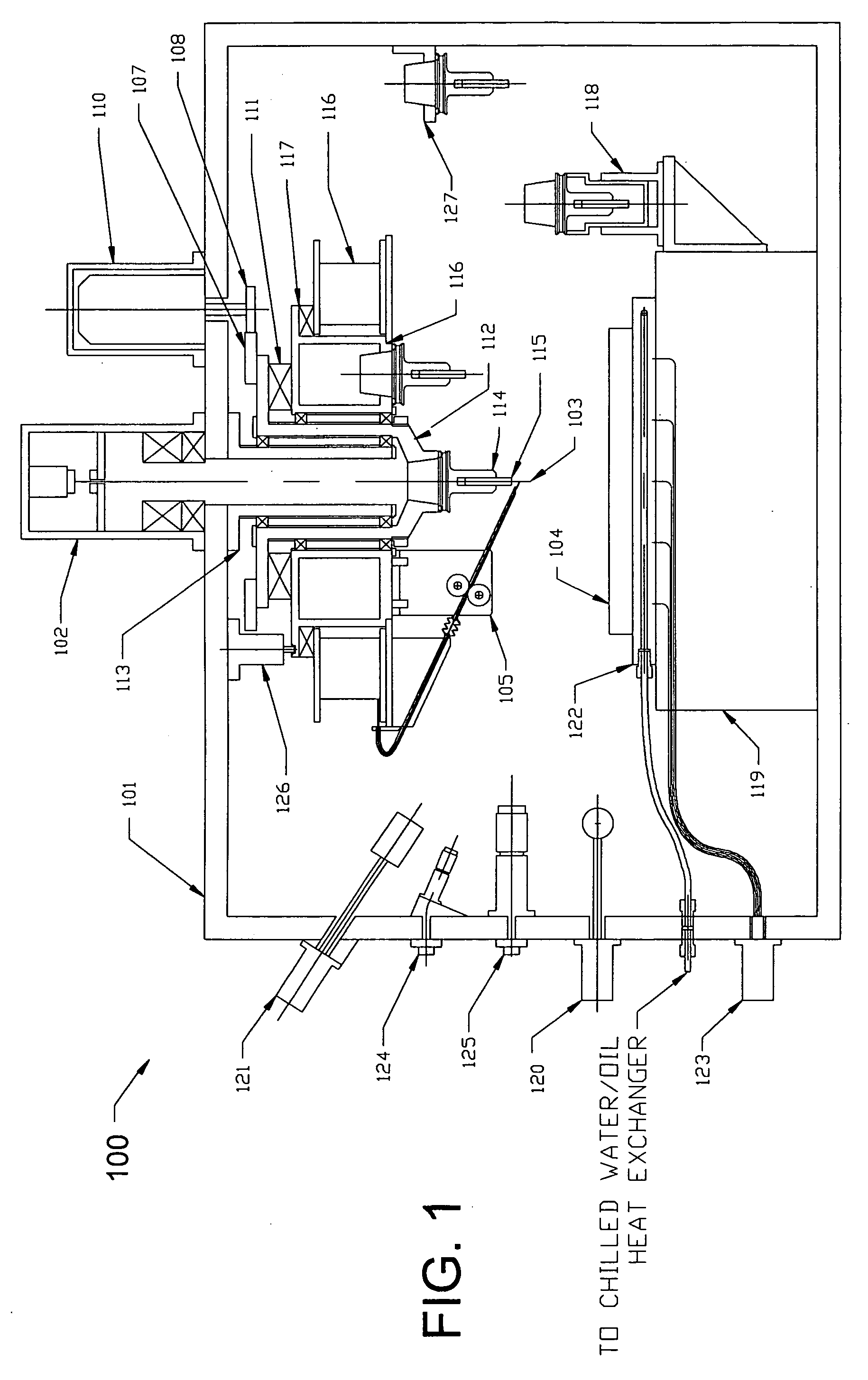
[0026] Material, typically in the form of powder or wire, is added to the molten pool in a controlled fashion as described in “Material Deposition System” (MDS) below. The wire delivery spool (preferred embodiment) is concentric and surrounding a motorized spindle, which is itself concentric with and surrounding the beam axis (interior to the wire spool). The wire spool is driven by the spindle when engaged via a pneumatic or electromagnetic clutch, which allows the wire orientation angle to be maintained at a constant angle to the deposition motion vector. The added material instantaneously melts upon contact with the energy beam and the molten pool. The molten pool quickly solidifies as the energy beam and / or the substrate continues to move, leaving behind a raised mound in the path of the beam, with the general appearance and shape of a welded bead. On any given layer, one or more of a series of parallel overlapping beads may be deposited, depending upon the thickness of the individual beads, the programmed bead overlap and the cross-section thickness of the layer being deposited, dictated by GAPP. The interim result is a “near-net” cross sectional shape, with an excess of approximately 0.050″ on each lateral surface and 0.025″ on the top surface.
[0027] After the near-net shape of each layer is established, the final configuration is established under the control of the Integrated Machining System (IMS). In the preferred embodiment, the IMS consists of a motorized spindle concentric with the beam axis, a series of tools in a tool holder ring, or carousel, concentric with and exterior to the spindle, but interior to the wire spool, and an automated tool changer that takes and replaces tools from the tool carousel to and from the spindle. The beam is temporarily deactivated while the milling head removes excess material from the width and height of the just-deposited layer, rendering a net shape (±0.005″) for that layer. For parts without draft angles, a three axis stage is adequate. For more complex parts requiring a 180 degree sphere of vector orientation, motion control is achieved through the five axes previously described. In an alternative configuration, without the rotating / tilting table, the XY work plate is configured as a “window frame” that can be flipped 180° to deposit on both sides of the part. Once the net shape is established for a given layer, the cutting tool is removed, allowing for the passage of the energy beam. A Non-Destructive Inspection (NDI) energy source, which may be in the form of an electron beam (the preferred embodiment, in which the electron beam also serves as the energy source for melting the feedstock), Xray, or ultrasound, operating under the control of the “Inspection and Repair System” (IRS) software, then traverses over the top of the just-milled surface to ensure that adequate fusion has taken place between the layers and that no voids have been introduced. Once the inspection process for the layer is complete, the deposition process is then begun on the next layer. In the event that a void or incomplete fusion is detected, a milling tool will be re-inserted into the spindle and a prescribed repair and re-inspect routine will be performed before proceeding to the next layer. The net result is a fully dense, functional, accurate, verifiable and repeatable three-dimensional structure.
[0028] For higher production rates, an alternative to the integration of the deposition and milling processes is described, which enables the deposition and milling processes to occur simultaneously rather than sequentially. In this embodiment, a pallet changer of a common variety simultaneously switches two palletized fixtures and parts that are in work at the same time, one being milled while the other is being deposited. The two processes can be tuned so that they each take approximately the same time, so that there is no time lag between sequences. This process obviously requires a much larger chamber (approximately twice as large) to accommodate two parts and simultaneous processes. Another benefit of separating the milling and deposition functions is that the mechanism becomes simpler and more rigid.
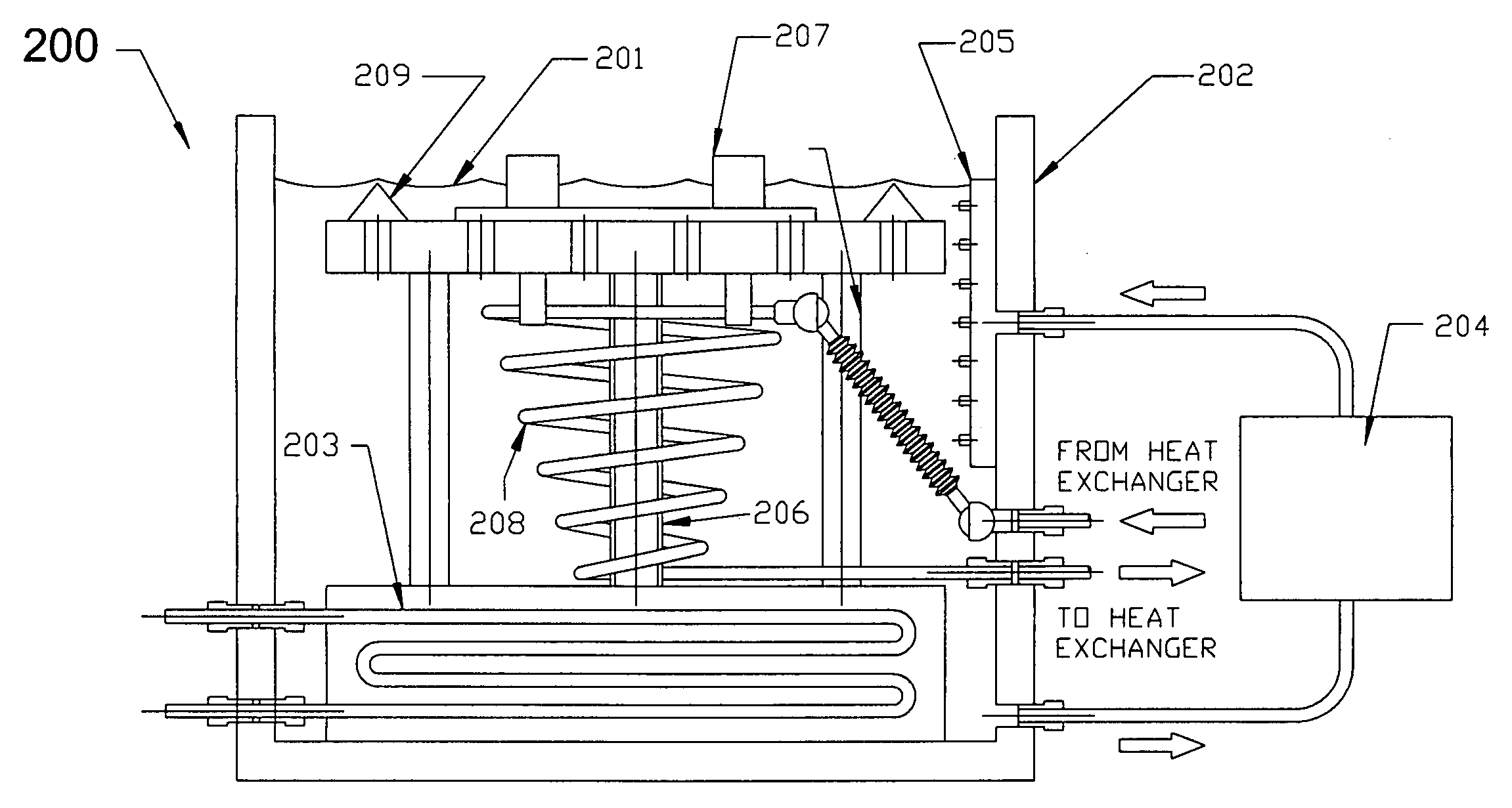
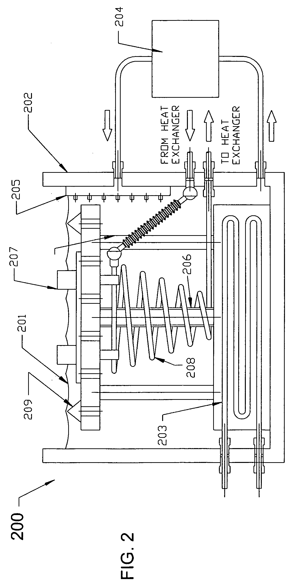
[0029] Excess heat is removed by a proactive cooling system. For low profile parts, consisting of approximately two to three inches of height, cooling is accomplished vial an internally cooled copper platen. The platen's internal cooling tubes are filled with oil, which is pumped outside of the chamber and the oil is cooled through a heat exchanger using chilled water as the heat sink. For taller parts requiring more direct heat removal, rather that being conducted through the previously deposited layers and the copper platen, a liquid metal coolant bath in employed, as shown in. The liquid metal bath resides in a pool below the platen, and as the platen is lowered to build each successive layer, the liquid metal passes through holes in the platen to surround the part. The liquid metal bath is cooled via an oil-cooled tube in the shape of an Archimedes spiral secured to the bottom of the vat and the underside of the platen. The heat is extracted from the oil as previously described. For further microstructure management of deposited metal, one or more transducers are placed on the platen to provide vibratory stress relief In the case employing the liquid metal bath, the transducer is submerged in the bath and the sound waves are propagated uniformly to the part through the bath. The temperature of the bath, oil, chilled water and application of sonic vibration are all controlled by the Heat and Microstructure Manager (HMM) software. The simultaneous application of sonic vibratory and thermal heat treatments to the deposit provides unique opportunities for synergistic effects and advanced microstructure management.

Problems solved by technology

In spite of the promise of dramatic reductions in both recurring costs (time, material and energy) and non-recurring cost (tooling) and having been in development for twenty years, DEMD has not been able to displace existing processes such as forging and casting, even in the most vulnerable applications.
There are five obstacles contributing to this impasse, both technical and economic.
Technically, the state of the art of DEMD systems has two major limitations: 1) the desired geometry and surface finishes cannot be achieved directly from deposited metal; 2) quality of the fusion, and particularly the absence of voids, cannot be assured.
Adding to the technological challenges are three economic disadvantages to current DEMD processes: 1) deposition rates are too low to make the processes economically competitive; 2) the feedstock (typically powder) is expensive to produce, and much of it gets wasted; 3) the deposited material still requires expensive post-deposit machining.
The main commercial limitation to this technology is that the parts made are typically non-functional, especially when the desired components are designed for structural or mechanical purposes and require high strength, temperature resistance, and / or fracture toughness.
These processes are able to product parts that approximate the material properties of cast metal, although persistent voiding remains a problem to this day.
The limitations of these processes are that deposition rates are low and are not void-free, surface finishes are rougher than are typically desired, and build-ups are limited to part profiles that do not include negative draft angles.
However, these processes still do not result in parts with accurate dimensions or good surface finishes (i.e., net shape), and most detrimentally, still have a tendency to produce deleterious voids and generally lack the desired material properties (e.g., strength, ductility, fracture toughness) consistent with their cast or forged counterparts.
This combination results in a layered buildup that produces less voids and higher deposition rates.
Its limitations are that the requirement for multiple multiaxis synchronicity between the fixturing system and the robotic welding system diminishes repeatability and reliability, and therefore produces less accurate “not-so-near-net” shapes.
Metallurgically, the open air environment introduces oxidation products which are largely deleterious in structural environments; and MIG welding produces a large heat affected zone (HAZ), causing (undesirable) non-uniform microstructure.
Most importantly, MIG welding in general affords little potential for automated control of the energy and mass transfer dynamics necessary for molten pool stability, because the only process variable available for control is the arc current.
None of the other energy sources used in RP have even half that control ability.
Undoubtedly this is an improvement over the accuracy of other previous wire feed systems (e.g., Brown et al, U.S. Pat. No. 4,323,756), but it is doubtful that it would be more accurate than stereolithography, whose resolution is the width of the laser, whereas Rabinovich's resolution is limited to the minimum diameter of his wire.
Additionally, as with any of the systems previously mentioned, the finer the resolution required, the slower the build process.
Namely, the Rabinovich's design lacks the rigidity to remove material in anything other that a surface smoothing mode, as Rabinovich represents the milling head's intended use.
The entire design is suspended and presupposes a C-frame construction that limits its ability to be further stiffened.
Secondly, Rabinovich's invention does not allow for the use of multiple metal removal tools or multiaxis tool orientation necessary for the finish machining of most complex structural components (he describes a millhead that can be angled, but shows a mill head that is fixed—an angled milling capability requires much more mechanical, structural and control features, and the attendant space—than his invention provides or affords).
Thirdly, Rabinovich's invention does not provide for heat management and microstructure control as the current invention does (not unsurprisingly, since his machine was not intended to melt the volumes of metal typically required for forgings and castings).
Although better capable of metal removal tasks than Rabinovich's invention, since it is essentially a mill, Prinz' design is simplistic and commercially impractical: it does not provide a means for automating the metal deposition process; the use of “complementary material” for overhangs (i.e., negative draft angled profiles) is both time consuming and wasteful; the use of specially ground milling cutters for machining underneath overhangs is both expensive and impractical, because periphery draft angles often change, even within the same layer.
Metallurgically, Prinz does not provide for any energy or heat management or microstructural control.
As is the case with Schneebeli's patent, Prinz' use of a conventional welding head has the same limitations for beam control.
Lasers, by contrast, need to rely upon cumbersome and relatively slow mechanical devices for beam control and phase transformations for energy requirements to achieve even a modicum of EB's beam parameter control.
Changing the position of the beam focus point, or shape of the beam, or beam energy density, or beam penetrability constitute equally challenging problems using laser physics, and trying to change multiple parameters simultaneously, much less all of parameters cited above (which is currently standard on most EB manufacturers' equipment—in spite of Maxumder's claims to the contrary), is not part of the current body of art and therefore currently impossible.
Differentiating the current invention from Maxunder et al's invention, their claims for high speed rapid prototyping do not apply to metal components, and his invention does not provide for use of wire feed stock or provide for interactive machining to improve dimensional accuracy and surface finishes.
However, powder has five serious drawbacks, four economical and one technical: Economically, 1) Powder is expensive to manufacture; 2) Powder requires an expensive inert carrier gas; 3) Powder cannot be deposited in very high volumes 4) A significant portion of powder is wasted in the process (up to 50%, depending on the process particulars).
Technically, powder has a tendency to produce voids and incomplete melting, especially on the fringes of the molten pool.
Technically, powder does not fuse as reliably as wire, because some of the powder is melted at the fringe of the molten pool, and is potentially incompletely melted before solidification takes place.
It also produces more voids due to its larger surface area.
This subject has been largely ignored in RP literature because larger challenges loom, such as void creation and detection, slow deposition rates and geometrical inaccuracy.
Heat management becomes more of an issue as the number of deposited layers increases and the molten pool gets further away from the substrate and underlying platen (typically copper, if employed) which acts as a heat sink.
Siedal's process is limited in deposition paths that are uni-directional and therefore limited to simplistic designs.
Finally, and perhaps most importantly, none of the current processes have the ability to produce void-free metal components.
This is the single most severe impediment to commercialization of DEMD technologies.

Method used


Image

  • Directed energy net shape method and apparatus
  • Directed energy net shape method and apparatus
  • Directed energy net shape method and apparatus

Examples


Embodiment Construction

[0047] Referring now to the drawing, and in particular to FIG. 1, a directed energy net shape apparatus according to the present invention is referred to generally by reference numeral 100. a directed energy net shape apparatus 100 includes an enclosure (vacuum chamber) 101.

[0048] The process requires a leak-free enclosure in order to prevent oxidation during the deposition process. In the case of the preferred embodiment, the energy source is an electron beam (EB), which performs best in a vacuum environment (10−5 torr) because in a vacuum there is minimal dissipating atmospheric ionization. However, it should be noted that partial vacuums and non-vacuum environments have been used for EB welding by using higher power guns to compensate for the atmospheric dissipation, and since the current invention does not require deep penetration or a very narrow beam, that option is available. However, it should also be noted that higher vacuum produces higher quality metal deposition (i.e., ...


PUM

PropertyMeasurementUnit
Shapeaaaaaaaaaa
Microstructureaaaaaaaaaa
Energyaaaaaaaaaa

Abstract

An electron gun mounted on top of a vacuum chamber, the gun emitting an electron beam vertically downward towards a substrate placed upon a three axis movable stage, creating a molten pool on the substrate, which is translated along an automatically generated, pre-programmed path in a plane normal to the beam by an automated numerical controller. A wire feeder and spool surround the beam in an annular ring, providing continuous material feed and constant orientation of the wire to the beam and pool, producing a high rate of material deposition and near net shape geometry. Integrated machining and inspection heads sequentially machine each layer to net shape then non-destructively inspect each layer. A heat and microstructure management system employs chilled oil or liquid metal coolant circulating through a vat surrounding the movable stage, supported by an actuator that gradually submerges the substrate as the deposited layers grow, the circulating coolant removing heat and machine chips. An integrated system architecture including six subsystems ensures density (no voids), accuracy, reliability, repeatability and verifiability: an energy management system manages energy input, including beam density, diameter and position; a geometry acquisition and path planning system acquires the cross-sectional two dimensional geometry from a three dimensional computer generated mathematical model and computes numerical control paths for deposit, machining and inspection processes; a material deposition system controls the placement and rate of material deposited; an integrated machining system subtracts excess material from each layer; an inspection and repair system detects, removes, refills and remachines defective areas; a heat management system eliminates excess heat by controlling the temperature and flow of a liquid metal coolant, and improves the microstructure of the deposited material via transducer generated sonic frequencies; a supervisory control synchronizes and coordinates the interaction between the various subsystems.

Description

CROSS-REFERENCE TO RELATED APPLICATIONS [0001] Provisional Patent Application Ser. No. 60 / 542,962, filed Feb. 9, 2004STATEMENT REGARDING FEDERALLY SPONSORED RESEARCH OR DEVELOPMENT [0002] Not Applicable INCORPORATION-BY-REFERENCE OF MATERIAL SUBMITTED ON A COMPACT DISC [0003] Not Applicable BACKGROUND OF THE INVENTION [0004] 1. Field of the Invention [0005] The present invention relates to the manufacture of three dimensional objects. [0006] 2. Description of Related Art [0007] The ultimate goal of all directed energy metal deposition (DEMD) processes and equipment is to develop faster and more cost effective methods of manufacturing non-prismatic three dimensional components, particularly those of high value due to the fact(s) that they are made of exotic and expensive alloys, are complexly shaped, and have high volume to weight ratios. These parts are commonly built today by one of three processes—casting, forging, or rolling. All three process have two important characteristics w...

Claims


Application Information

Patent Timeline
IPC IPC(8): B23K15/00B23K26/08B23K26/14B23K26/34
CPCB22F3/1055B23K15/002B23K15/0046B23K15/0086B23K26/032B23K26/0853B23K35/0244B23K26/1411B23K26/147B23K26/34B22F2003/1056B23K26/3206B23K26/345B23K26/122B23K26/1224B23K26/32B23K26/342B23K26/144B23P6/00B23P23/04B23K2103/50Y02P10/25B22F12/33B22F12/37B22F12/90B22F10/50B22F10/25B22F12/20B22F12/53
Inventor CARBONE, FRANK L.
Owner CARBONE FR L
Why Eureka
Eureka Blog
Learn More