Nano graphene platelet-reinforced composite heat sinks and process for producing same

a graphene platelet and composite heat sink technology, applied in the field of composite materials, to achieve the effects of reducing/eliminating the possibility of graphene platelet flaking, thermal conductivity, and high surface scratch resistan

Active Publication Date: 2014-08-14
GLOBAL GRAPHENE GRP INC
View PDF6 Cites 85 Cited by
  • Summary
  • Abstract
  • Description
  • Claims
  • Application Information

AI Technical Summary

Benefits of technology

[0041]In a presently invented integrated heat sink, the graphene platelet-reinforced composite has a thermal conductivity greater than 20 W / mK (preferably greater than 50 W / mK, more preferably greater than 100 W / mK, further preferably greater than 200 W / mK, even more preferably greater than 400 W / mK, and most preferably greater than 500 or 1,000 W / mK), and / or a tensile strength greater than 60 MPa (preferably greater than 100 MPa, more preferably greater than 200 MPa, and most preferably greater than 300 MPa). The presently invented NGP-reinforced composite also has a high surface scratch resistance and reduced / eliminated possibility of graphene platelets flaking off from the heat sink surface. No conventional composites possess such a combination of outstanding properties.

Problems solved by technology

For instance, as new and more powerful chip designs and light-emitting diode (LED) systems are introduced, they consume more power and generate more heat.
This has made thermal management a crucial issue in today's high performance systems.
This further increases the difficulty of thermal dissipation.
Actually, thermal management challenges are now widely recognized as the key barriers to industry's ability to provide continued improvements in device and system performance.
Typically, heat transfer between a solid surface and the air is the least efficient within the system, and the solid-air interface thus represents the greatest barrier for heat dissipation.
However, there are several major drawbacks or limitations associated with the use of metallic heat sinks:(1) One drawback relates to the relatively low thermal conductivity of a metal (the best being 400 W / mK for Cu and 80-200 W / mK for Al alloy).(2) In addition, the use of copper or aluminum heat sinks can present a problem because of the weight of the metal, particularly when the heating area is significantly smaller than that of the heat sink.
If metallic heat sinks are employed, the sheer weight of the metal on the board can increase the chances of the board cracking or of other undesirable effects, and increase the weight of the component itself.(3) Many metals do not exhibit a high surface thermal emissivity and thus do not effectively dissipate heat through the radiation mechanism.(4) For outdoor applications (e.g. LED-based street lights), metals have severe corrosion issues.
The mechanical properties (tensile strength, flexural strength, and moduli) of flexible graphite and resin-impregnated flexible graphite are relatively poor.
By impregnating the exfoliated graphite with a resin, the resulting composite exhibits an even lower thermal conductivity (typically (2) Flexible graphite foils are of low strength, low rigidity, and poor structural integrity.
The high tendency for flexible graphite foils to get torn apart makes them difficult to handle in the process of making a heat sink.
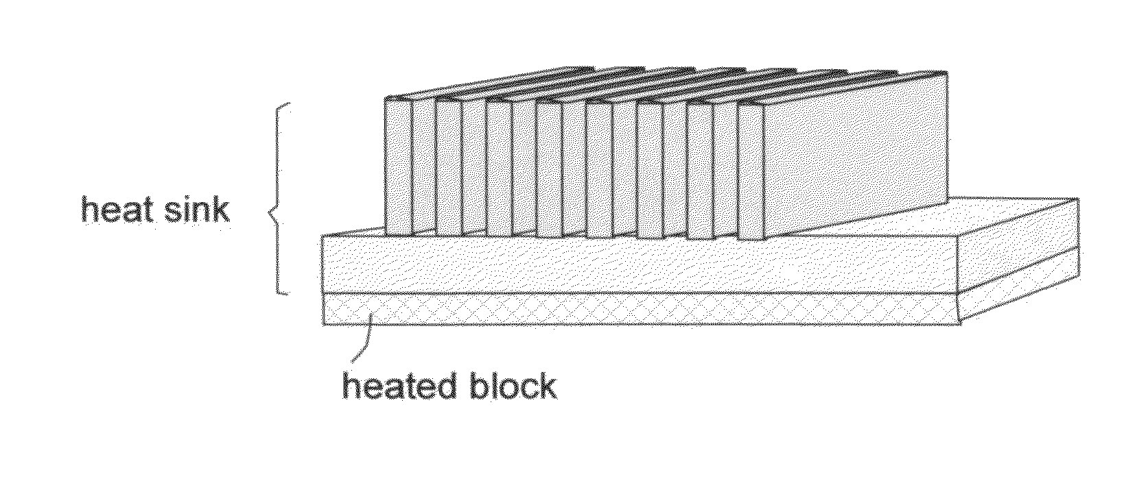
As a matter of fact, the flexible graphite sheets (typically 50-200 μm thick) are so “flexible” that they are not sufficiently rigid to make a fin component material for a finned heat sink.(3) Flexible graphite sheets are not geometrically or structurally amenable to impregnation of resin into the sheet-like structure.
Even after puncturing the flexible graphite sheet with glass fibers, for instance, to create resin entry channels, there is a limited amount of resin that can be impregnated into the sheet, resulting in poor structural strength.
Quite surprisingly, mixing of graphite worms with a resin prior to roll-pressing leads to poor structural strength as well even though the resulting composite can contain a large proportion of resin.(4) Another very subtle, largely ignored or overlooked, but critically important feature of FG foils is their high tendency to get flaky with graphite flakes easily coming off from FG sheet surfaces and emitting out to other parts of a microelectronic device.
These highly electrically conducting flakes (typically 1-200 μm in lateral dimensions and >100 nm in thickness) can cause internal shorting and failure of electronic devices.(5) Both resin-free flexible graphite and resin-impregnated FG (with resin impregnating step occurring before or after roll-pressing) are not conducive to mass production of finned heat sink structures.
It is virtually impossible to use mass production processes (such as extrusion, stamping, forging, and die casting that are commonly used for making aluminum heat sinks, or injection molding for making conductive filler-reinforced plastic-based heat sinks) to make FG-based heat sinks without some kind of subsequent bonding or assembling operations.
A major shortcoming of such heat sinks is their high cost.
This cost is related directly to the labor required to individually arrange each fin on some sort of support or substrate (a base or core) and high production cycle time.
Further, bonding between a fin and a base is not always reliable and the long-term reliability of flexible graphite-based finned heat sinks is highly questionable.
However, ultra-thin film or paper sheets (<10 μm) are difficult to produce in mass quantities, and difficult to handle when one tries to incorporate these thin films as a heat sink material.
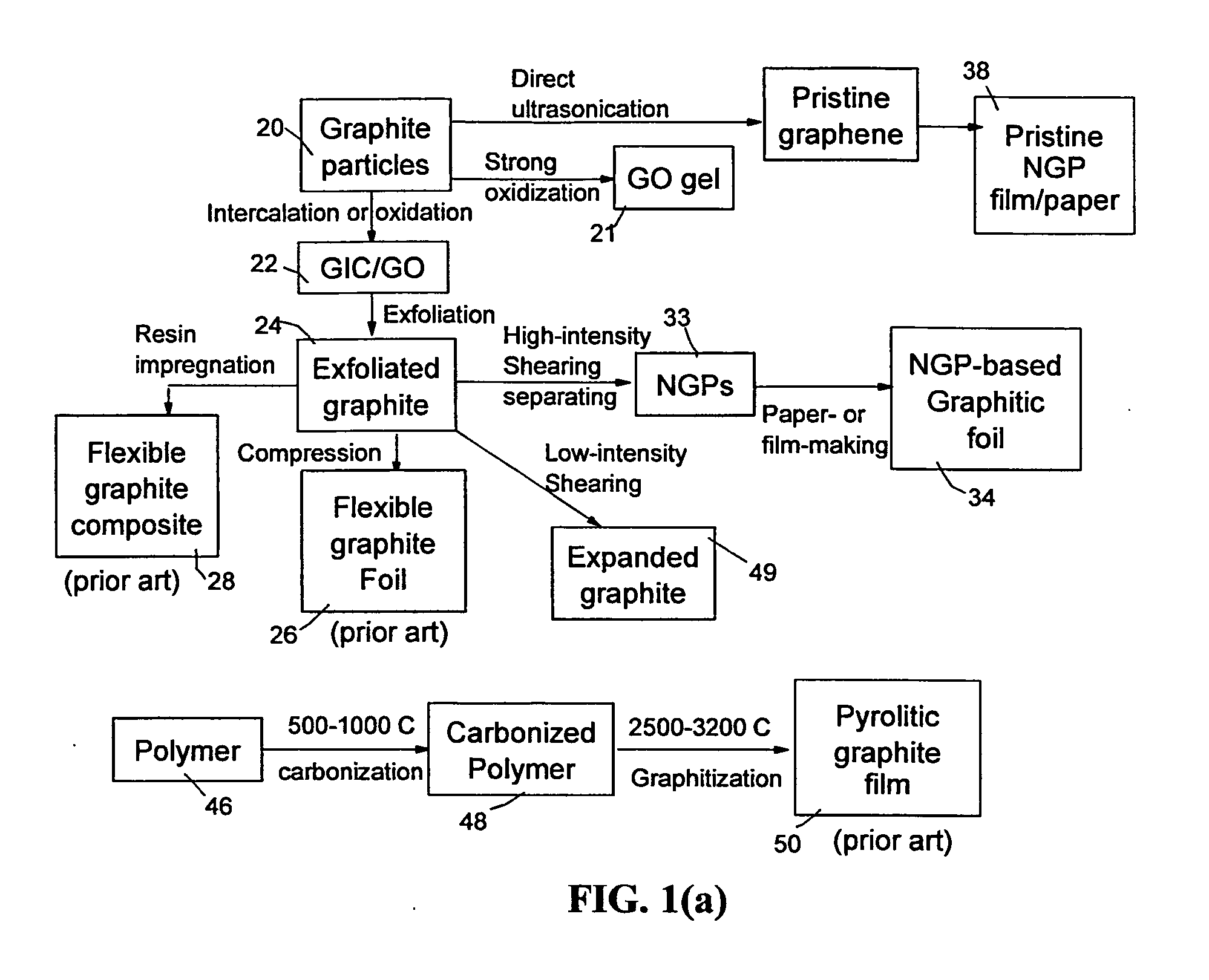
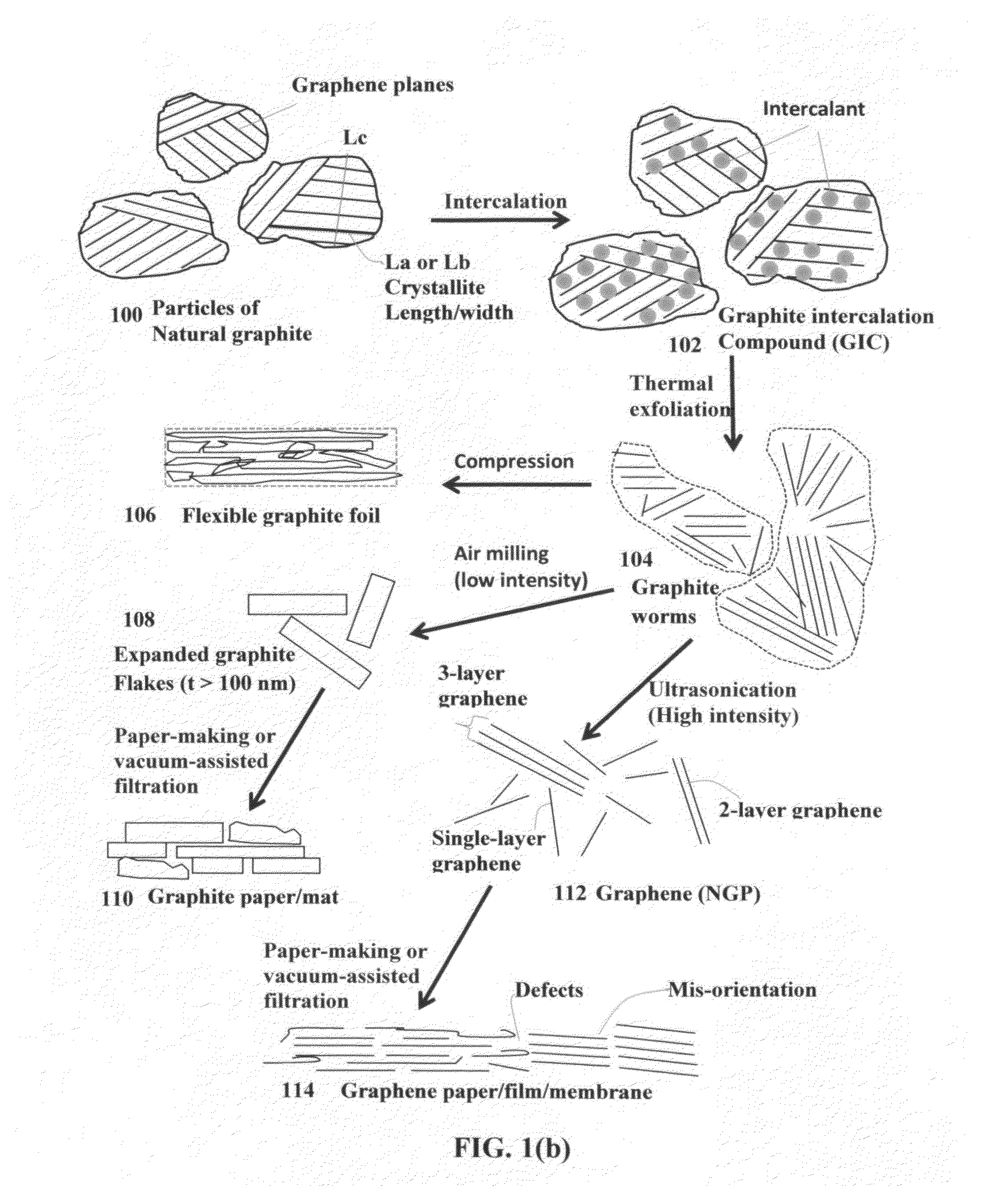
In general, a paper-like structure or mat made from platelets of graphene, GO, or RGO (e.g. those paper sheets prepared by vacuum-assisted filtration process) exhibit many defects, wrinkled or folded graphene sheets, interruptions or gaps between platelets, and non-parallel platelets (e.g. SEM image in FIG. 3(b)), leading to relatively poor thermal conductivity, low electric conductivity, and low structural strength.
These papers or aggregates of discrete NGP, GO or RGO platelets alone (without a resin binder) also have a tendency to get flaky, emitting conductive particles into air.
However, there was no teaching of using these infiltrated NGPs as a finned heat sink.
NGP-reinforced polymers have been known to exhibit very poor flow behavior when the NGP amount is higher than 15-20% by weight.
Hence, it would not be considered feasible to produce NGP composite heat sinks having a fin thinner than 2 mm.
Again, these aggregates have a great tendency to have graphite particles flaking and separated from the film surface, creating internal shorting problem for the electronic device containing these aggregates.
They also exhibit low thermal conductivity unless made into thin films (10 nm-300 nm, as reported by Haddon, et al) which are very difficult to handle in a real device manufacturing environment.
However, the metal matrix is too heavy and the resulting metal matrix composite does not exhibit a high thermal conductivity.
More significantly, all these prior art materials and related processes are not amenable to mass production of finned heat sinks cost-effectively.
In fact, there has been no known report on using these materials for finned heat sink applications.
It is technically utmost challenging to maintain such an ultrahigh pressure at such an ultrahigh temperature.
This is a difficult, slow, tedious, energy-intensive, and very expensive process.
Furthermore, carbonization of certain polymers (e.g. polyacrylonitrile) involves the emission of toxic species.
This entails a thermo-mechanical treatment of combined mechanical compression and ultra-high temperature for an extended period of time in a protective atmosphere; a very expensive, energy-intensive, and technically challenging process.
The process requires ultra-high temperature equipment (with high vacuum, high pressure, or high compression provision) that is not only very expensive to make but also very expensive and difficult to maintain.
Even with such extreme processing conditions, the resulting PG (including HOPG) still possesses many defects, grain boundaries, and mis-orientations (neighboring graphene planes not parallel to each other), resulting in less-than-satisfactory in-plane properties.
Typically, the best prepared HOPG sheet or block remains far from being a graphite single crystal; instead, it typically still contains many grains or crystals and a vast amount of grain boundaries and defects.
All PG film production processes do not allow for impregnation of a resin matrix.
PG or HOPG films, being weak, non-rigid, and not easily processable suffer from the same shortcomings as flexible graphite intended for use to construct finned heat sinks.
Furthermore, PG or HOPG films are extremely expensive.
No prior art material meets this set of technical requirements.

Method used


Image

  • Nano graphene platelet-reinforced composite heat sinks and process for producing same
  • Nano graphene platelet-reinforced composite heat sinks and process for producing same
  • Nano graphene platelet-reinforced composite heat sinks and process for producing same

Examples


example 1

Preparation of Discrete Nano Graphene Platelets (NGPs) and Expanded Graphite Flakes

[0088]Chopped graphite fibers with an average diameter of 12 μm and natural graphite particles were separately used as a starting material, which was immersed in a mixture of concentrated sulfuric acid, nitric acid, and potassium permanganate (as the chemical intercalate and oxidizer) to prepare graphite intercalation compounds (GICs). The starting material was first dried in a vacuum oven for 24 h at 80° C. Then, a mixture of concentrated sulfuric acid, fuming nitric acid, and potassium permanganate (at a weight ratio of 4:1:0.05) was slowly added, under appropriate cooling and stirring, to a three-neck flask containing fiber segments. After 16 hours of reaction, the acid-treated graphite fibers or natural graphite particles were filtered and washed thoroughly with deionized water until the pH level of the solution reached 6. After being dried at 100° C. overnight, the resulting graphite intercalatio...

example 2

Preparation of Single-Layer Graphene Sheets from Meso-Carbon Micro-Beads (MCMBs)

[0091]Meso-carbon microbeads (MCMBs) were supplied from China Steel Chemical Co. This material has a density of about 2.24 g / cm3 with a median particle size of about 16 μm. MCMB (10 grams) were intercalated with an acid solution (sulfuric acid, nitric acid, and potassium permanganate at a ratio of 4:1:0.05) for 72 hours. Upon completion of the reaction, the mixture was poured into deionized water and filtered. The intercalated MCMBs were repeatedly washed in a 5% solution of HCl to remove most of the sulphate ions. The sample was then washed repeatedly with deionized water until the pH of the filtrate was neutral. The slurry was dried and stored in a vacuum oven at 60° C. for 24 hours. The dried powder sample was placed in a quartz tube and inserted into a horizontal tube furnace pre-set at a desired temperature, 1,080° C. for 45 seconds to obtain a graphene material. TEM and atomic force microscopic stu...

example 3

Preparation of Pristine Graphene Sheets / Platelets

[0092]In a typical procedure, five grams of graphite flakes, ground to approximately 20 μm or less in sizes, were dispersed in 1,000 mL of deionized water (containing 0.1% by weight of a dispersing agent, Zonyl® FSO from DuPont) to obtain a suspension. An ultrasonic energy level of 85 W (Branson 5450 Ultrasonicator) was used for exfoliation, separation, and size reduction of graphene sheets for a period of 15 minutes to 2 hours.


PUM

PropertyMeasurementUnit
weight fractionaaaaaaaaaa

Abstract

An integrated heat sink article composed of a heat collection member and at least one heat dissipation member integral to the heat collection member, wherein the heat collection member is configured to be in thermal contact with a heat source, collects heat from the heat source, and dissipates heat through the at least one heat dissipation member, and further wherein the heat sink is formed of a nano graphene platelet-reinforced composite having nano graphene platelets or sheets (NGPs) as a first reinforcement phase dispersed in a matrix material and the first reinforcement phase occupies a weight fraction of 1-90% based on the total composite weight. Preferably, these NGPs, alone or in combination with a second reinforcement phase, are bonded by an adhesive and constitute a continuous 3-D network of electron- and phonon-conducting paths.

Description

FIELD OF THE INVENTION[0001]The present invention relates generally to the field of composite materials for heat dissipation applications and, more particularly, to a finned heat sink formed of a graphene platelet-reinforced composite. This composite exhibits a combination of an exceptionally high thermal conductivity and structural integrity not achievable with the conventional carbon nanofiber-, carbon nanotube-, graphite particle-, carbon black-resin composites, flexible graphite sheet, and resin-impregnated flexible graphite composites.BACKGROUND OF THE INVENTION[0002]Advanced thermal management materials are becoming critical for today's microelectronic, photonic, and photovoltaic systems. For instance, as new and more powerful chip designs and light-emitting diode (LED) systems are introduced, they consume more power and generate more heat. This has made thermal management a crucial issue in today's high performance systems. Systems ranging from active electronically scanned r...

Claims


Application Information

Patent Timeline
Patent Type & Authority Applications(United States)
IPC IPC(8): F28F21/02
CPCF28F21/02Y10S977/833B82Y30/00H01L23/373H01L23/3737H01L2924/0002H01L2924/00H01L23/3735
Inventor LIN, YI-JUNZHAMU, ARUNAJANG, BOR Z.
Owner GLOBAL GRAPHENE GRP INC
Why Eureka
Try Eureka