Anode active material-coated graphene sheets for lithium batteries and process for producing same

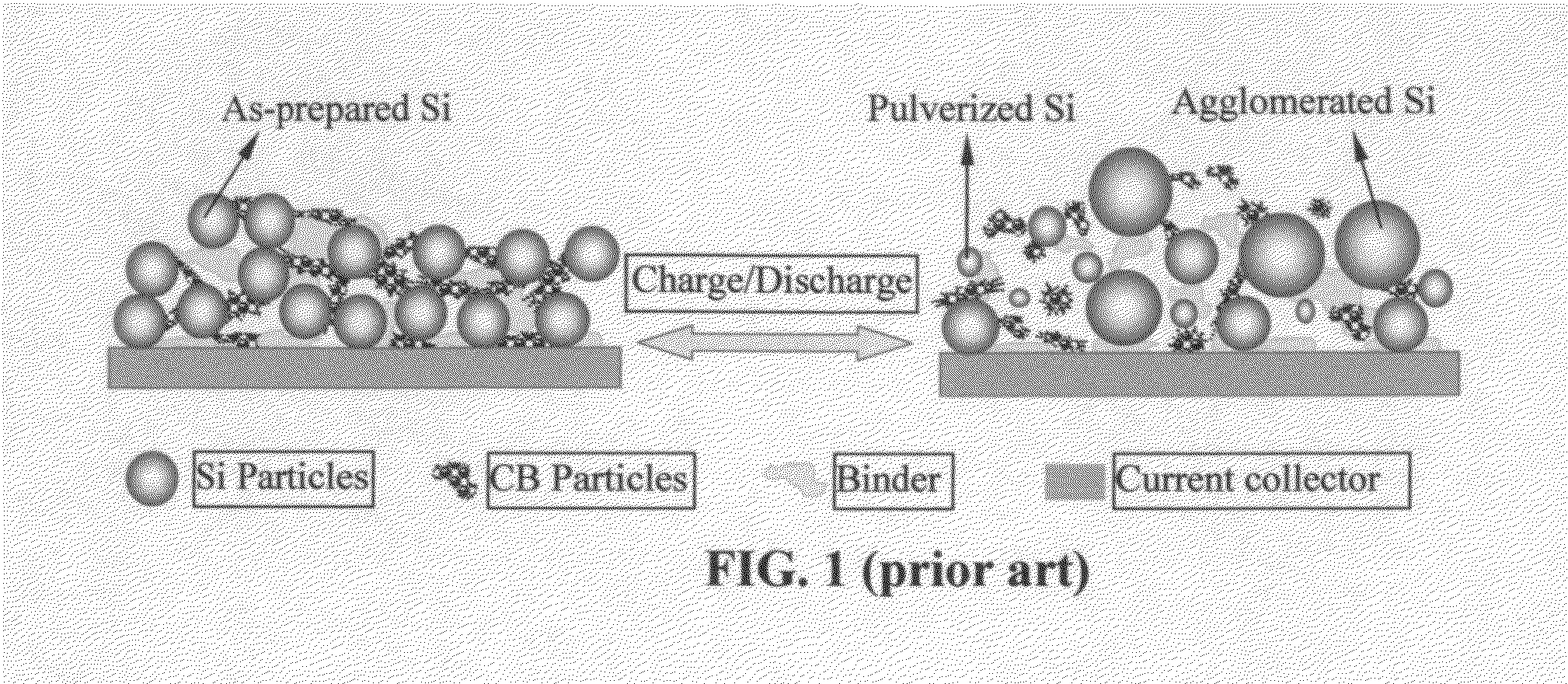
a lithium battery and active material technology, applied in the field of graphene-enhanced anode active material for lithium batteries, can solve the problems of loss of contacts between active particles and conductive additives, loss of contacts between anode active materials and current collectors, and severe pulverization (fragmentation of alloy particles), and achieve enhanced li-ion insertion and hybridization. the effect of more than double the specific capacity

Active Publication Date: 2015-02-12
GLOBAL GRAPHENE GRP INC
View PDF9 Cites 89 Cited by
  • Summary
  • Abstract
  • Description
  • Claims
  • Application Information

AI Technical Summary

Benefits of technology

[0014]After our discovery of graphene providing an outstanding support for anode active materials, many subsequent studies by others have confirmed the effectiveness of this approach. For instance, Wang, et al. investigated self-assembled TiO2-graphene hybrid nanostructures for enhanced Li-ion insertion [D. Wang, et al. “Self-Assembled TiO2-Graphene Hybrid Nanostructures for Enhanced Li-Ion Insertion.”ACS Nano, 3 (2009) 907-914]. The results indicate that, as compared with the pure TiO2 phase, the specific capacity of the hybrid was more than doubled at high charge rates. The improved capacity at a high charge-discharge rate was attributed to increased electrode conductivity afforded by a percolated graphene network embedded into the metal oxide electrodes. However, all these earlier studies were focused solely on providing a network of electron-conducting paths for the anode active material particles and failed to address other critical issues, such as ease of anode material processing, electrode processability, electrode tap density (the ability to pack a dense mass into a given volume), and long-term cycling stability. For instance, the method of preparing self-assembled hybrid nanostructures is not amenable to

Problems solved by technology

However, in the anodes composed of these materials, severe pulverization (fragmentation of the alloy particles) occurs during the charge and discharge cycles due to expansion and contraction of the anode active material induced by the insertion and extraction of the lithium ions in and out of the anode active material.
The expansion and contraction, and the resulting pulverization of active material particles lead to loss of contacts between active particles and conductive additives and loss of contacts between the anode active material and its current collector.
These adverse effects result in a significantly shortened charge-discharge cycle life.
Such a reaction is undesirable since it is a source of irreversible capacity loss.(2) depositing the electrode active material in a thin film form directly onto a current collector, such as a copper foil.
However, such a thin film structure with an extremely small thickness-direction dimension (typically much smaller than 500 nm, often necessarily thinner than 100 nm) implies that only a small amount of active material can be incorporated in an electrode (given the same electrode or current collector surface area), providing a low total lithium storage capacity and low lithium storage capacity per unit electrode surface area (even though the capacity per unit mass can be large).
Such a thin-film battery has very limited scope of application.
Unfortunately, when an active material particle, such as Si particle, expands during the battery charge step, the protective coating is easily broken due to the mechanical weakness and/o brittleness of the protective coating materials.
These protective materials are all very brittle, weak (of low strength), and/or non-conducting (e.g., ceramic or oxide coating).
(d) The protective material must not provide any significant amount of defect sites that irreversibly trap lithium ions.
The prior art protective materials all fall short of these requirements.
Furthermore, in most cases, the electrode was

Method used


Image

  • Anode active material-coated graphene sheets for lithium batteries and process for producing same
  • Anode active material-coated graphene sheets for lithium batteries and process for producing same
  • Anode active material-coated graphene sheets for lithium batteries and process for producing same

Examples


example 1

Graphene Oxide from Sulfuric Acid Intercalation and Exfoliation of MCMBs

[0099]MCMB 2528 meso-carbon microbeads were supplied by Alumina Trading, which was the U.S. distributor for the supplier, Osaka Gas Chemical Company of Japan. This material has a density of about 2.24 g / cm3 with a median particle size of about 22.5. MCMB 2528 (10 grams) were intercalated with an acid solution (sulfuric acid, nitric acid, and potassium permanganate at a ratio of 4:1:0.05) for 48 hours. Upon completion of the reaction, the mixture was poured into deionized water and filtered. The intercalated MCMBs were repeatedly washed in a 5% solution of HCl to remove most of the sulphate ions. The sample was then washed repeatedly with deionized water until the pH of the filtrate was neutral. The slurry was dried and stored in a vacuum oven at 60° C. for 24 hours. The dried powder sample was placed in a quartz tube and inserted into a horizontal tube furnace pre-set at a desired temperature, 800° C. for 30 sec...

example 2

Oxidation and Exfoliation of Natural Graphite

[0100]Graphite oxide was prepared by oxidation of graphite flakes with sulfuric acid, sodium nitrate, and potassium permanganate at a ratio of 4:1:0.05 at 30° C. for 48 hours, according to the method of Hummers [U.S. Pat. No. 2,798,878, Jul. 9, 1957]. Upon completion of the reaction, the mixture was poured into deionized water and filtered. The sample was then washed with 5% HCl solution to remove most of the sulfate ions and residual salt and then repeatedly rinsed with deionized water until the pH of the filtrate was approximately 7. The intent was to remove all sulfuric and nitric acid residue out of graphite interstices. The slurry was dried and stored in a vacuum oven at 60° C. for 24 hours.

[0101]The dried, intercalated (oxidized) compound was exfoliated by placing the sample in a quartz tube that was inserted into a horizontal tube furnace pre-set at 1,050° C. to obtain highly exfoliated graphite. The exfoliated graphite was dispers...

example 3

Preparation of Anode Active Material-Coated Graphene Sheets and Secondary Particles

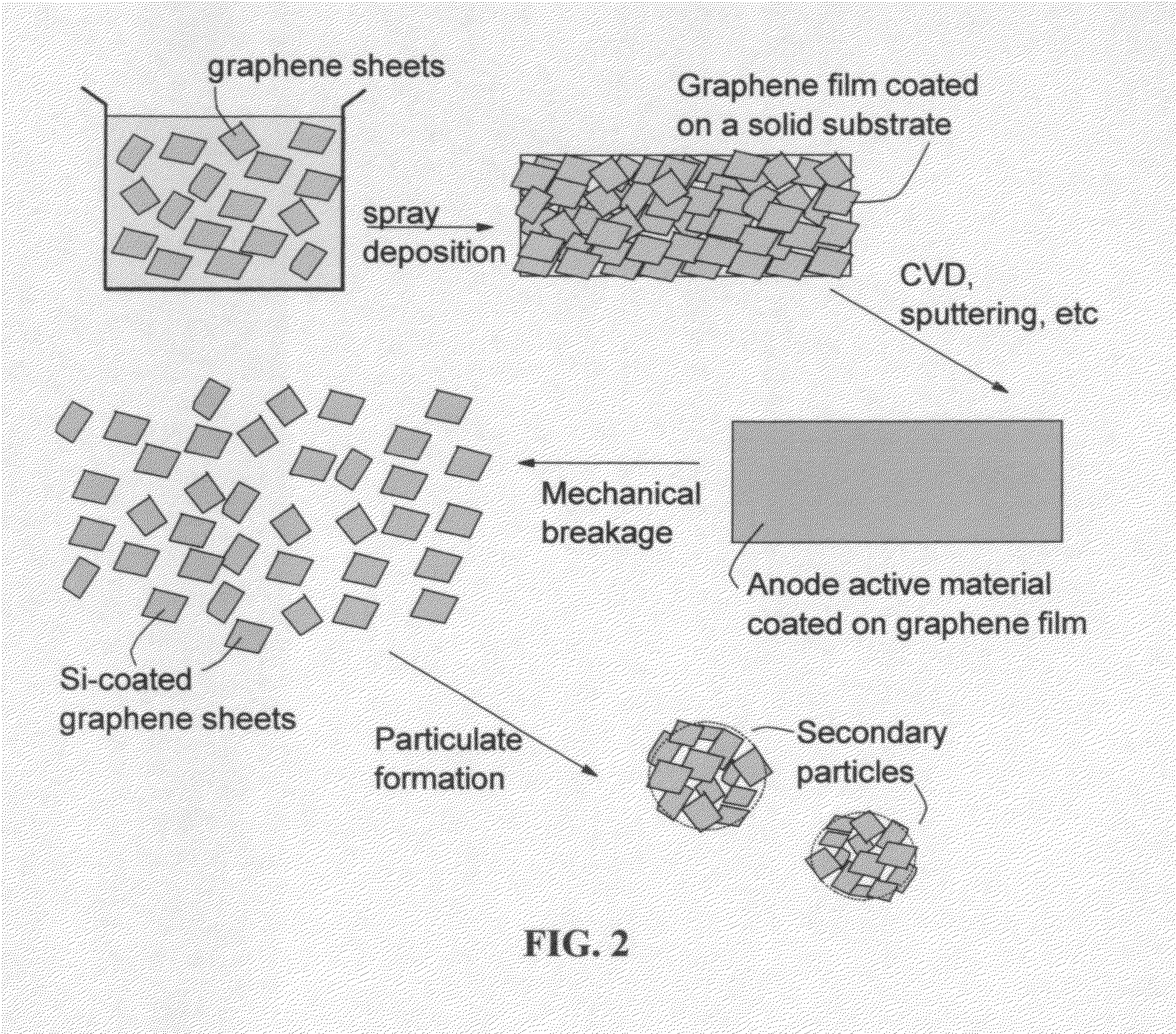
[0102]Continuous graphene films coated with an anode active material were prepared from CVD (Si), sputtering (Co3O4 and SnO), and physical vapor deposition (Sn). The coated film was broken, cut into pieces, and then air jet milled to obtain small pieces of active material-coated graphene sheets.

[0103]For the preparation of graphene-enhanced particulates, an amount of a selected electrode active material powder (control sample, no supporting graphene sheet) or active material-coated graphene sheets was added to a desired amount of GO suspension to form a precursor mixture suspension with a solid content of approximately 10% by weight. After thorough mixing in an ultrasonication reactor, the suspension was then spray-dried to form the graphene-enhanced secondary particles (particulates).

[0104]The anode active materials studied in this example include Si, Co3O4, Sn, and SnO. The cathode active materials ...


PUM

PropertyMeasurementUnit
Fractionaaaaaaaaaa
Fractionaaaaaaaaaa
Fractionaaaaaaaaaa

Abstract

The present invention provides a process for producing a graphene-enhanced anode active material for use in a lithium battery. The process comprises (a) providing a continuous film of a graphene material into a deposition zone; (b) introducing vapor or atoms of a precursor anode active material into the deposition zone, allowing the vapor or atoms to deposit onto a surface of the graphene material film to form a sheet of an anode active material-coated graphene material; and (c) mechanically breaking this sheet into multiple pieces of anode active material-coated graphene; wherein the graphene material is in an amount of from 0.1% to 99.5% by weight and the anode active material is in an amount of at least 0.5% by weight, all based on the total weight of the graphene material and the anode active material combined.

Description

FIELD OF THE INVENTION[0001]The present invention relates generally to the fields of lithium-ion batteries and, in particular, to a graphene-enhanced anode active material for a lithium-ion battery.BACKGROUND[0002]The most commonly used anode materials for lithium-ion batteries are natural graphite and synthetic graphite (or artificial graphite) that can be intercalated with lithium and the resulting graphite intercalation compound (GIC) may be expressed as LixC6, where x is typically less than 1. The maximum amount of lithium that can be reversibly intercalated into the interstices between graphene planes of a perfect graphite crystal corresponds to x=1, defining a theoretical specific capacity of 372 mAh / g.[0003]Graphite or carbon anodes can have a long cycle life due to the presence of a protective surface-electrolyte interface layer (SEI), which results from the reaction between lithium and the electrolyte (or between lithium and the anode surface / edge atoms or functional groups...

Claims


Application Information

Patent Timeline
IPC IPC(8): H01M4/36H01M4/52H01M4/04H01M4/38H01M10/28H01M4/44H01M4/46H01M4/485H01M4/58H01M4/62H01M4/42
CPCH01M4/366H01M2004/027H01M4/52H01M4/0428H01M4/0423H01M4/0426H01M4/386H01M4/387H01M4/42H01M4/44H01M4/463H01M4/485H01M4/58H01M10/28H01M4/625H01M4/133H01M4/134H01M4/1393H01M4/1395H01M4/587H01M10/0525Y02E60/10Y02P70/50Y02T10/70
Inventor WANG, YANBOJANG, BOR Z.HE, HUIZHAMU, ARUNA
Owner GLOBAL GRAPHENE GRP INC
Why Eureka
Try Eureka