Nanoparticle comprising nanoshell of thickness less than the bulk electron mean free path of the shell material

a nanoparticle and shell material technology, applied in the direction of nuclear engineering, natural mineral layered products, synthetic resin layered products, etc., can solve the problems of limited utility of these solutions, inability to position the plasmon resonance at technologically important wavelengths, and application of solid metal nanoparticles. achieve the effect of enhancing polarization at the plasmon resonan

Inactive Publication Date: 2008-05-13
RICE UNIV
View PDF37 Cites 77 Cited by
  • Summary
  • Abstract
  • Description
  • Claims
  • Application Information

AI Technical Summary

Benefits of technology

[0043]The enhanced polarizability at the plasmon resonance of these compositions could be used in chemical sensing or chemical analysis applications, where information concerning the properties of molecules adsorbed onto the nanoparticle surface is obtained. Such compositions may permit the use of surface enhanced raman scattering (SERS) to

Problems solved by technology

A serious practical limitation to realizing many applications of solid metal nanoparticles is the inability to position the plasmon resonance at technologically important wavelengths.
However, the utility of these solutions is limited because their plasmon resonance is confined to relatively narrow wavelength ranges and cannot readily be shifted.
However, gold-sulfide particle diameters are limited to sizes of approximately 40-45 nm with a thin gold shell (less than 5 nm).
(1997) An additional limitation of such particles as defined by Zhou et al. is that both the core and the shell are grown as a result of a single chemical reaction, thus limiting the choice of the core material and the shell material

Method used


Image

  • Nanoparticle comprising nanoshell of thickness less than the bulk electron mean free path of the shell material
  • Nanoparticle comprising nanoshell of thickness less than the bulk electron mean free path of the shell material
  • Nanoparticle comprising nanoshell of thickness less than the bulk electron mean free path of the shell material

Examples


example i

General Method for Metal Nanoshell Colloid Based Synthesis

[0051]Versatile methods for the synthesis of nanoparticle cores and metal shells of defined sizes have been developed and are described below. Generally, the method comprised the following steps:[0052](1) first a dielectric or semiconductor nanoparticle core was obtained and dispersed in solution;[0053](2) then 1-2 nm metal-like “seed” colloids were attached to the surface of the nanoparticle core via molecular linkages, covering the core surface with a discontinuous metal colloid layer;[0054](3) finally, additional metal was deposited onto the metal-like adsorbates by a solution phase chemical reduction reaction.

[0055]This nanoparticle assembly method was carried out with silica nanoparticles and gold colloid. Both commercially available silica nanoparticles and silica nanoparticles grown in situ were used successfully. The organosilane linkage molecule 4-aminopropyltriethoxy silane was absorbed onto the nanoparticle core. G...

example ii

Core Particle Synthesis

[0056]Initially a core material for the nanoparticle was prepared. This material had a spherical shape, and was approximately uniform in size. The silica particles produced in the following procedure had a standard deviation of less than 10% (4% is routinely achievable).

[0057]The method of Stober (1968), incorporated herein by reference to the extent it provides such methods, was used to produce monodisperse silicon dioxide particle cores. Tetraethyl orthosilicate (TEOS) 99.999% was obtained from Aldrich Chemical Co., sodium hydroxide was from Fluka Chemical Co. and highly purified water was obtained from a Millipore “TOTALQ” system that included “MILLIQUV” and “MILIQRO” filters. All glassware was cleaned with chromic acid solution and thoroughly rinsed with “TOTALQ” water.

[0058]Variations in water, base concentration, and TEOS concentration were used to produce monodisperse silica spheres of various sizes. Temperature and electrolyte concentration also affect...

example iii

Linker Molecule Attachment

[0060]To assemble a metallic shell around an inner layer frequently required the use of linker molecules. These molecules were chemically linked to the inner layer and served to bind atoms, ions, atomic or molecular clusters of the conducting shell to the inner layer. The conducting shell atoms that bound to the linkers were used as nucleation sites for reduction of the additional atoms or molecules to complete the shell. One method used to attach gold particles to silicon dioxide was to treat the particles with aminopropyltriethoxy silane (APTES). The silanol end groups of the APTES molecules attach covalently to the silica core extending their amine groups outward as a new termination of the particle surface.

[0061]In this method, 10 ml of a silica particle suspension such as prepared in Example III, was added to a 50 ml glass beaker. Next, pure aminopropyltriethoxy silane (APTES) was added to the solution. Based on estimates enough silane was added to coa...


PUM

PropertyMeasurementUnit
Lengthaaaaaaaaaa
Fractionaaaaaaaaaa
Fractionaaaaaaaaaa

Abstract

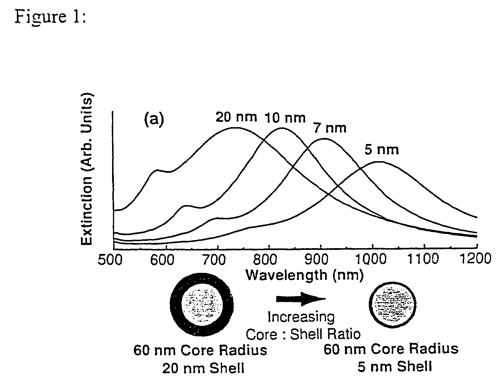
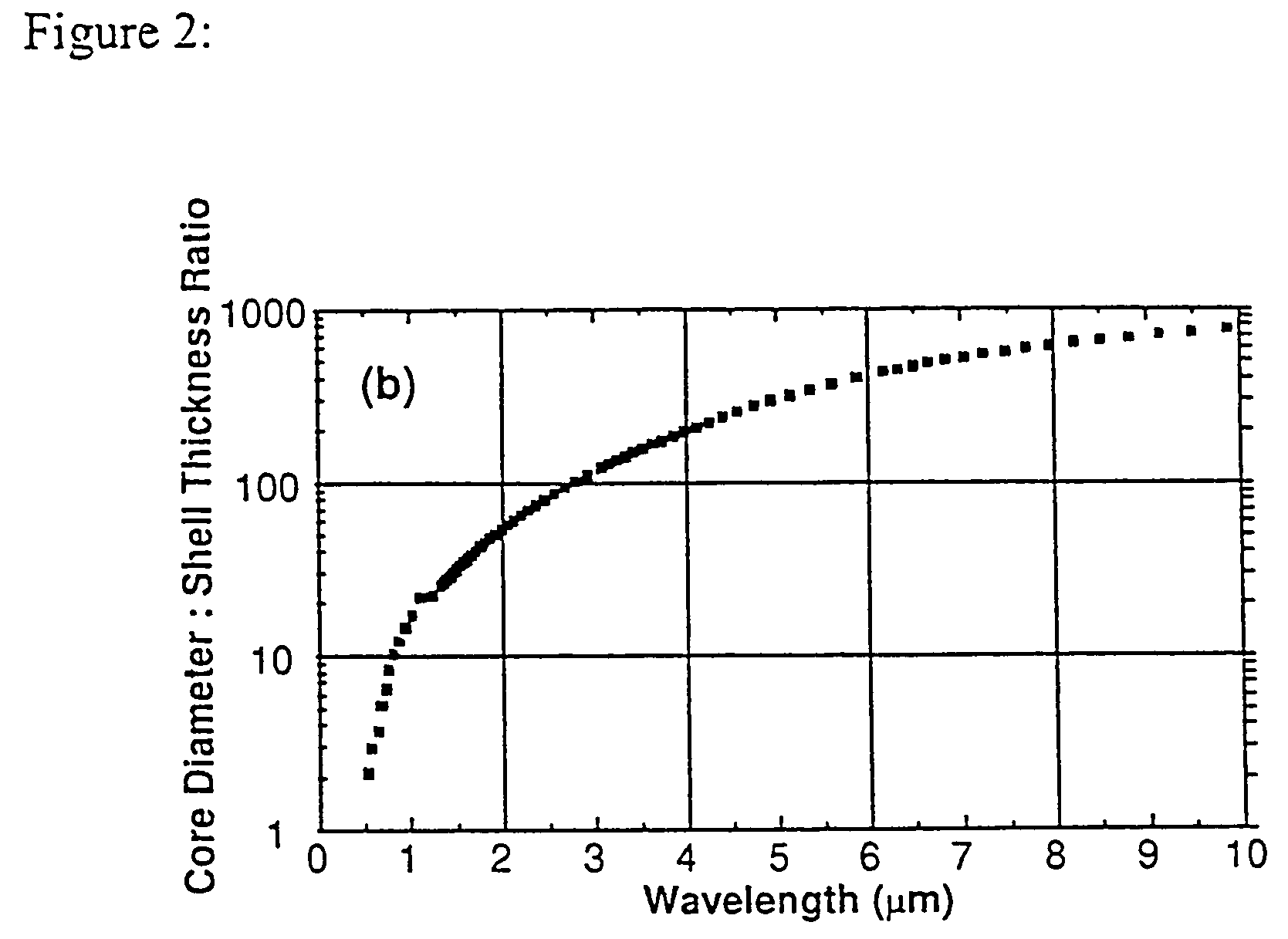
The present invention is for particulate compositions and methods for producing them that can absorb or scatter electromagnetic radiation. The particles are homogeneous in size and are comprised of a nonconducting inner layer that is surrounded by an electrically conducting material. The ratio of the thickness of the nonconducting layer to the thickness of the outer conducting shell is determinative of the wavelength of maximum absorbance or scattering of the particle. Unique solution phase methods for synthesizing the particles involve linking clusters of the conducting atoms, ions, or molecules to the nonconducting inner layer by linear molecules. This step can be followed by growth of the metal onto the clusters to form a coherent conducting shell that encapsulates the core.

Description

CROSS-REFERENCE TO RELATED APPLICATIONS[0001]This application relies for priority on the following two provisional applications: the first application is entitled Metal Nanoshells and is to Oldenburg et al., and was filed Mar. 12, 1997 and has serial No. 60 / 040,971; the second application is entitled Metal Nanoshells is to Oldenburg et al., and was filed on Mar. 14, 1997 and the serial number of that application is No. 60 / 040,570. These applications are specifically included herein by reference.STATEMENT REGARDING FEDERALLY SPONSORED RESEARCH OR DEVELOPMENT[0002]The research that resulted in this invention was funded by the Office of Naval Research, N00014-97-1-0217, and the National Science Foundation, ECS-9258118.BACKGROUND OF THE INVENTION[0003]It is known that solid metal nanoparticles (i.e. solid, single metal spheres of uniform composition and nanometer dimensions) possess unique optical properties. In particular, metal nanoparticles (especially the coinage metals) display a p...

Claims


Application Information

Patent Timeline
IPC IPC(8): B32B5/16A61K41/00B01J13/02B22F1/054B22F1/18C08K9/02C09C1/30C09K3/00G02F1/355G21K1/10
CPCA61K41/0042B22F1/0018B22F1/02B82Y30/00C08K9/02C09C1/3054C09C1/3081C09C1/309C09K3/00G02F1/355B01J13/02Y10T428/2993B82Y5/00B82Y15/00C01P2002/82C01P2002/84C01P2004/04C01P2004/12C01P2004/32C01P2004/38C01P2004/50C01P2004/54C01P2004/61C01P2004/62C01P2004/64C01P2004/80C01P2006/22C01P2006/33C01P2006/40C01P2006/60G01N21/658Y10S428/913Y10S977/835Y10S977/777Y10S977/832Y10T428/2998Y10T428/2991B22F1/054B22F1/056B22F1/18
Inventor OLDENBURG, STEVEN J.AVERITT, RICHARD D.HALAS, NANCY J.
Owner RICE UNIV
Why Eureka
Try Eureka