Three dimensional format biochips

a biochip and three-dimensional technology, applied in the field of three-dimensional format biochips, can solve the problems of low sensitivity, large capital investment, and high production cost of the first generation of nucleic acid biochips, and achieve the effects of improving sensitivity, simple, and high sensitivity

Inactive Publication Date: 2009-12-29
BIOCEPT INC
View PDF18 Cites 60 Cited by
  • Summary
  • Abstract
  • Description
  • Claims
  • Application Information

AI Technical Summary

Benefits of technology

[0022]The present invention provides improved biochips and rapid, simple, cost effective methods for constructing such biochips and improved assays resulting from the use of such biochips. Biomolecular probes and other binding agents can be bound prior to or simultaneously with polymerization of a particular gel, thereby permitting a simple, one or two step process to produce such a biochips which have increased sensitivity, superior stability both in use and in shelf-life, and improved cost effectiveness in manufacture.
[0024]The present invention provides a biochip in the form of an array of optically clear PEG or PPG-based polymeric microdroplets arranged on a solid substrate, and it provides the capability of forming as many as 1,000 individual reaction cells per square centimeter. Each cell would typically contain at least one binding entity immobilized generally within the volume of the microdroplet or upon its surface. By altering the different binding entities in the cells in the array in a known fashion, an efficient screening of biological samples or compounds for hybridization, or for binding interactions or activities, can be performed and quantitated. These cells are preferably three-dimensional in form which maximizes the amount of binding entity contained in each and thereby maximizes detection sensitivity.

Problems solved by technology

First generation nucleic acid biochips are very expensive to produce, requiring large capital investments, process engineering and equipment.
Furthermore, the method of forming oligonucleotides in a single layer on a substrate results in a low sensitivity biochip often requiring an expensive laser confocal fluorescence microscope for adequate detection of DNA specifically hybridized to the chip.
Still, as will be readily appreciated by those of skill in the art, production of biochips in accordance with the disclosures of the '257 and '019 patents is not only expensive but also time-consuming.
Another polyacrylamide-based biochip described U.S. Pat. No. 5,770,721 is based upon the polymerization of acrylamide monomers by a free radical initiation or ultraviolet radiation process; however, this polyacrylamide-based gel biochip is constructed in a multi-step process that is lengthy and labor-intensive.
Production of such a biochip requires cumbersome multi-step processing including polymerization and binding to the surface of the glass substrate; mechanical or laser cutting to form micro-squares of gel matrix on the substrate; activation step using hydrazines; and finally reaction with the oligonucleotides.
Moreover, the potential reaction of the oligonucleotides with the hydrazine groups would form unstable morpholine derivatives, resulting in a very short shelf half-life for the biochip of approximately thirty-six hours at room temperature.
From the standpoint of studying protein-ligand, protein-protein, protein-DNA interaction, there are presently a number of known methods, all of which possess significant limitations in that they are either cumbersome, expensive, require large amounts of proteins or are not suitable for the rapid high throughput analysis of protein interactions.
This method requires relatively large amounts of capture proteins for suitable immobilization to agarose beads, and it is not suitable for the rapid high throughput screening of protein interactions.
Even though this method may relatively frequently be used, it is slow and cumbersome, requires significant molecular biology expertise, and does not lend itself to the rapid, high throughput screening of protein-protein interaction in an economical way.
This method is slow and cumbersome, requires significant biochemistry expertise, and likewise does not lend itself to the rapid high throughput analysis of protein interactions.
This method has a number of limitations, e.g. large molecular weight proteins are difficult to display, and only very few of a phage's filamentous proteins are appropriate for such use.
In addition, conformational constrictions of the displayed protein have been known to decrease its affinity and consequently affect its ability to bind to its natural ligand.
Because the above methods of protein immobilization to provide binding entities generally employ direct chemical conjugation of proteins onto the surface of a substrate, these methods embody a major limitation in resultant loss of protein function, due either to inappropriate chemical conjugation at active sites or to loss of original conformation.
When such occurs, only a low amount of immobilized protein remains active and results in detection difficulties and low assay sensitivity.
In addition, the complexity and lack of precision of these methods generally render them unsuitable for use in fabrication of high-density microarrays for high throughput use.
Limitations of the method include difficulties in preparing precise, small cells on the biochip and in potential destructive effects on the capture protein during crosslinking.
This photoactivation approach used for the immobilization of proteins to a biochip appears limited to certain photoactivation chemistries involving acrylamide polymers, and moreover, the use of free radical photochemistry may cause potential free radical damage to the capture proteins being used in biochips fabricated in such fashion.
While the described methodology may be suitable for such purposes, these processes do not form optically clear hydrogels of controlled geometry which would be suitable for biochip use.
Additionally, using such methods without inhibiting potential conjugation to protein side chains may very likely cause undesirable crosslinking of the protein to the polymer, and extensive crosslinking may diminish or destroy the native conformation of the protein and thus reduce the bioactivity of the protein which would render such process unsuitable for high precision binding assays for which biochips are used.

Method used


Image

  • Three dimensional format biochips
  • Three dimensional format biochips
  • Three dimensional format biochips

Examples


example 1

Preparation of a DNA Biochip and Test

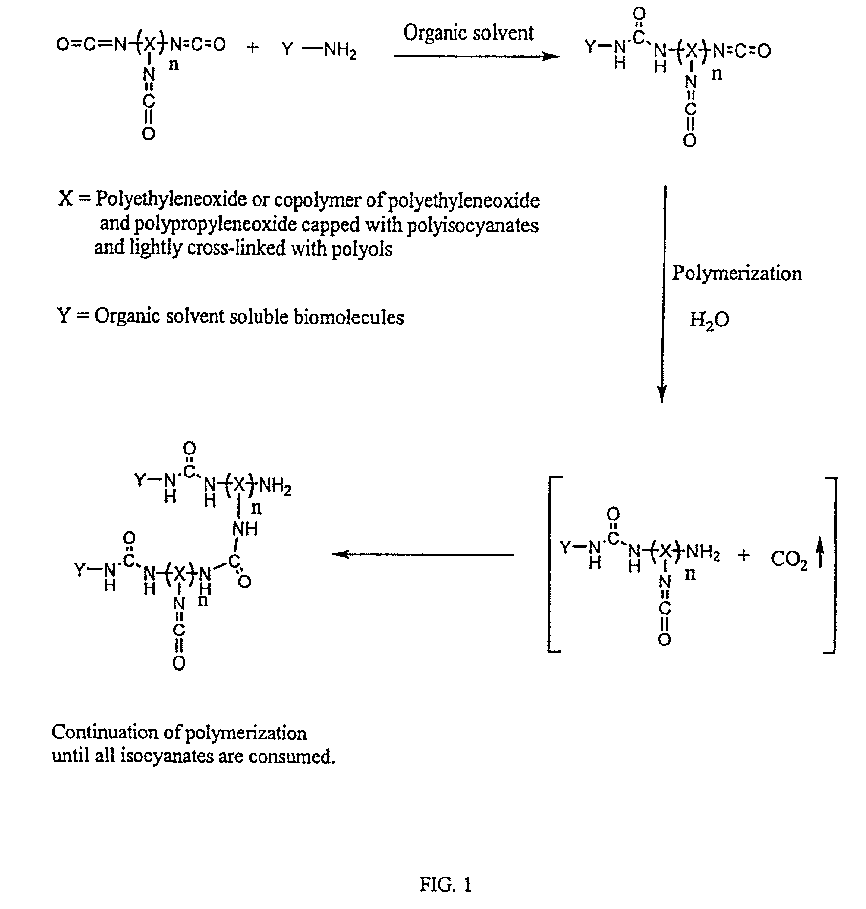
[0071]A solution of 0.025 g of Hypol PreMa G-50 was prepared in 0.15 g acetonitrile. Next, a solution of 1 mg DNA (0.3 μm), having hexaneamine at its 5′ end and having the sequence NH2(CH2)6-CATTGCTCAAAC-3′ (SEQ ID No:1), in 0.32 g of a 50 mM NaHCO3 aqueous buffer at pH 8.0 was prepared. The DNA solution was added to the prepolymer solution and thoroughly mixed. Droplets of the resulting solution were manually spotted on a silanated glass slide using a capillary microtube. As a negative control, hydrogel droplets containing no DNA were spotted next to the DNA-containing hydrogel droplets.

[0072]The glass slide, having the hydrogel droplets thereon, was submersed into washing buffer (10 mM sodium phosphate buffer with 0.5 M NaCl and 0.1% SDS at pH 7.0) for 30 minutes to remove organic solvents and block the remaining active sites to prevent non-specific binding of test DNA. Next, the slide was treated with 1 mg of a complementary fluorescence-label...

example 1a

Preparation of an Array DNA Biochip and Test in Human β-globin Gene Sequence Detection

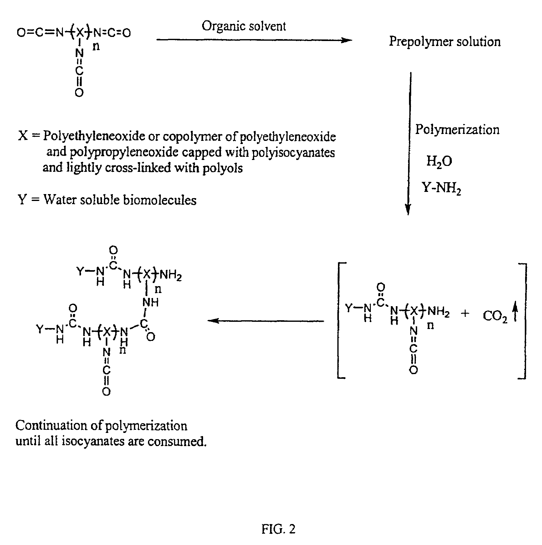
[0073]A DNA biochip was prepared as follows:[0074]1. The following two reactant solutions were prepared:[0075]Solution A=0.1 g Hypol Pre-Ma G-50 in 0.33 g acetonitrile and 0.33 g NMP (Weight ratio of 4.5:15:15)[0076]Solution B=1 mg of oligonucleotide in 1 ml of 50 mM borate buffer at pH 8.0[0077]2. Solution A (34.5 parts) was mixed with Solution B (65.5 parts), and the resultant solution microspotted onto a glass slide. Microspotting was performed with an open configuration pin, CT MicroPipets DP-120 μm, supplied by Conception Technologies.[0078]3. The microspotted slides were placed into a controlled humidifier chamber for one hour and then washed with a washing buffer for 10 minutes, completing the preparation of the biochips.

[0079]Testing of such a biochip is performed by hybridization with a target sample carrying a fluorescent tag or the like at different concentrations in a hybridization buff...

example 2

Use of Additives (glycerol / trehalose) to Enhance Bioactivity

[0086]The following example shows that unreactive proteins, simple carbohydrates and humectants have a protective effect on hydrogel-immobilized antibody activities of these biochips, enhancing overall signal and assay performance.

[0087]Panel A —Trehalose. In this experiment, aliquotes of a trehalose stock solution, 50% w / v D(+) trehalose dihydrate in 50 mM sodium borate buffer, pH 8.0, were added to 50 μl final volume hydrogel formulation. The formulation also included 3.5 weight % final concentration HYPOL PreMA® G-50 hydrogel prepolymer (premixed stock solution containing HYPOL, acetonitrile, N-methyl-2-pyrrolidinone at a w / w / w ratio of 1:3:3, respectively), anti-transferrin (4 mg / ml phosphate buffered saline IX (PBS), 2 μl bovine IgG (50 / mg / ml in PBS and 1.25% glycerol). The amount of trehalose was varied from 0 to 10 μl, corresponding to a final w / v percentage of 0, 1%, 2%, 5% and 10% trehalose. A blank hydrogel spot w...


PUM

PropertyMeasurementUnit
thickaaaaaaaaaa
thickaaaaaaaaaa
thickaaaaaaaaaa

Abstract

A biochip is formed with a plurality of optically clear hydrogel cells attached to the top surface of a solid substrate in the form of an array. Each of the cells is formed of a hydrogel of polyethylene glycol, polypropylene glycol or a copolymer thereof having reactive isocyanate groups. Binding entities are immobilized in these cells, which entities are effective to selectively hybridize to or sequester a target biomolecule. Different binding entities are immobilized in different cells in an array to create a biochip that can be used to assay for a number of target biomolecules.

Description

[0001]This application claims priority from U.S. Provisional Application Ser. No. 60 / 243,699 filed Oct. 26, 2000. This application is a continuation-in-part of International Application PCT / US00 / 11282 filed Apr. 26, 2000, which was a continuation-in-part of U.S. Ser. No. 09 / 299,831, filed Apr. 26, 1999, and now U.S. Pat. No. 6,174,683. The disclosures of these applications are incorporated herein by reference.FIELD OF THE INVENTION[0002]Agents that selectively bind to DNA, RNA or analogs, such as peptide nucleic acids (PNAs) are of significant interest to molecular biology and medicinal chemistry as they may be developed into gene-targeted drugs for diagnostic and therapeutic applications and may be used as tools for sequence-specific modification of DNA. Additionally, such reagents may be used as tools for determining gene sequences and for functional gene analyses.[0003]Until recently, the processes of gene discovery, characterization and functional gene analysis have been difficu...

Claims


Application Information

Patent Timeline
Patent Type & Authority Patents(United States)
IPC IPC(8): C40B40/00C40B40/10C40B60/14G01N33/543G01N33/544G01N33/545
CPCG01N33/545G01N33/54353G01N33/5436G01N33/544B01J2219/00351B01J2219/00585B01J2219/00587B01J2219/00596B01J2219/00605B01J2219/00612B01J2219/00617B01J2219/00621B01J2219/00626B01J2219/0063B01J2219/00637B01J2219/00644B01J2219/00659B01J2219/00725C40B40/10C40B60/14B01J2219/00497
Inventor FAGNANI, ROBERTOHAHN, SOONKAPDONG, XIAOFANPIRCHER, TONYMATSUMOTO, SANDRATSINBERG, PAVEL
Owner BIOCEPT INC
Why Eureka
Try Eureka