Method and apparatus for treating waste water

a technology for treating waste water and waste water, applied in water/sewage treatment by neutralisation, electrodialysis, water/sewage treatment by ion exchange, etc., can solve the problems of interconnection resistance, difficult to etch a copper layer in a semiconductor, signal delay due to interconnection resistance, etc., to achieve good gas separation, increase the decomposition rate, and the effect of large specific surface area

Inactive Publication Date: 2006-11-02
EBARA CORP
View PDF1 Cites 38 Cited by
  • Summary
  • Abstract
  • Description
  • Claims
  • Application Information

AI Technical Summary

Benefits of technology

[0016] As treatment processes usable for removing an oxidizing agent, such as hydrogen peroxide, contained in the above-described water to be treated, there may be catalytic decomposition with activated carbon, catalytic decomposition with a noble metal catalyst, e.g. a titania-supported platinum catalyst or an alumina-supported platinum catalyst, catalytic decomposition with a manganese dioxide catalyst, electrolysis, ultraviolet-rays treatment, ozone addition, decomposition treatment with a reducing agent such as hydrazine, sodium thiosulfate or sodium sulfite, and enzymatic hydrolysis with an H2O2 degrading enzyme (catalase), etc. When using a platinum catalyst such as an alumina-supported platinum catalyst, it is preferred to use a honeycomb-shaped catalyst because of its large specific surface area, its good gas-separability and increased decomposition rate.
[0017] Further, a honeycomb-shaped catalyst can be provided with successive openings in the flow direction, so that particles smaller than the opening area may be passed through the openings without being accumulated in the catalyst. The honeycomb-shaped catalyst can therefore be advantageously used for decomposing an oxidizing agent contained in slurry-containing waste water such as CMP waste water.

Problems solved by technology

For example, in fabrication processes for semiconductor devices such as semiconductor integrated circuits, demands for semiconductor devices having finer interconnections or elements have further increased in recent years to thereby cause a problem of signal delay due to interconnection resistance.
It is difficult to etch a copper layer in a semiconductor chip to form a pattern in the semiconductor chip.
Because a concentration of copper in waste water produced chemical mechanical polishing (CMP) process or waste water produced in copper plating is normally 100 mg / l or lower, heretofore there has not been used an electrolytic deposition process due to the problem of operating voltage rise.

Method used


Image

  • Method and apparatus for treating waste water
  • Method and apparatus for treating waste water
  • Method and apparatus for treating waste water

Examples


example 1

[0193] In this example, nonwoven fabric having the following characteristics was used as a base material for producing a cation-exchange nonwoven fabric. The base nonwoven fabric was formed by thermal fusion of composite fiber which consists of a core portion of polypropylene and a sheath portion of polyethylene.

TABLE 1Component of corePolypropyleneComponent of sheathPolyethyleneAreal density50 g / m2Thickness0.55 mmDiameter of fiber15-40 μmProducing method of nonwoven fabricthermal fusionPorosity91%

[0194] A gamma ray was irradiated to the nonwoven fabric substrates under a nitrogen atmosphere and then immersed into a solution of glycidyl methacrylate (GMA). Thus, the nonwoven fabric substrates were reacted with the solution to form graft-polymerized nonwoven fabric having a graft ratio of 175%. The graft-polymerized nonwoven fabric was immersed into a mixed solution of sodium sulfite, isopropyl alcohol, and water, for sulfonation. Thus, a cation-exchange nonwoven fabric was produce...

example 2

[0195] Experiment was carried out using the experimental apparatus shown in FIG. 22. In FIG. 22, the reference numeral 134 denotes a cation-exchange membrane, 136 denotes treated water, 138 denotes concentrated water, 141 denotes an electrolytic deposition apparatus, and 142 denotes water to be treated. In the separation treatment, the cation-exchange nonwoven fabric having sulfo group was used as an ion exchanger in the desalting chamber 135, and the cation-exchange nonwoven fabric having sulfo group was used as an ion exchanger in the concentrating chamber 137. As electrode material, the cathode 140 was made of expanded metal (material: SUS), and the anode 139 was made of expanded metal (material: titanium coated with platinum). Sulfuric acid was supplied to the cathode chamber so that a pH of the liquid became 1.5 or less.

[0196] In the recovery of copper, plate-like electrodes were employed. The anode material was titanium coated with platinum, and the cathode material was coppe...

example 3

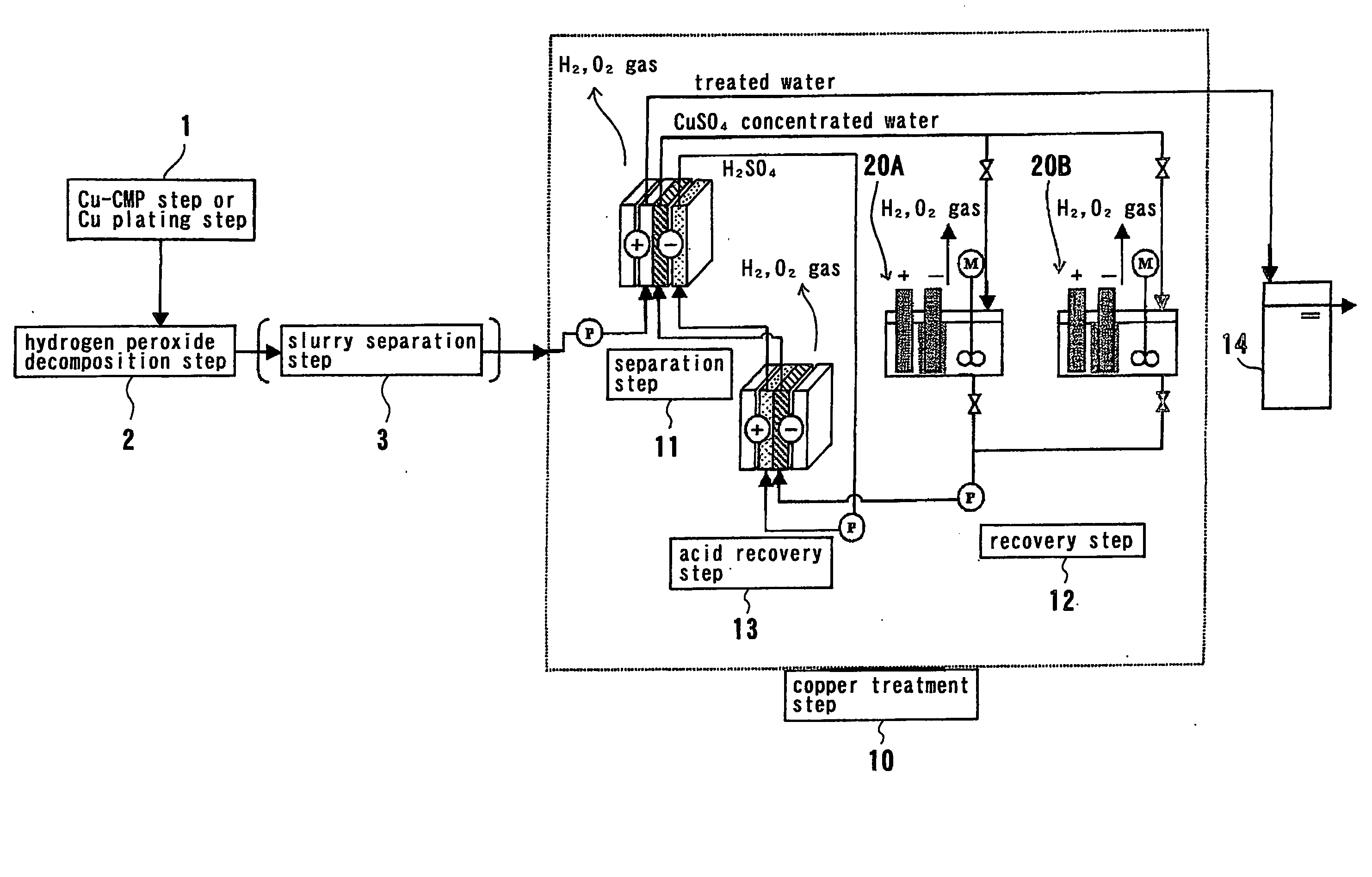
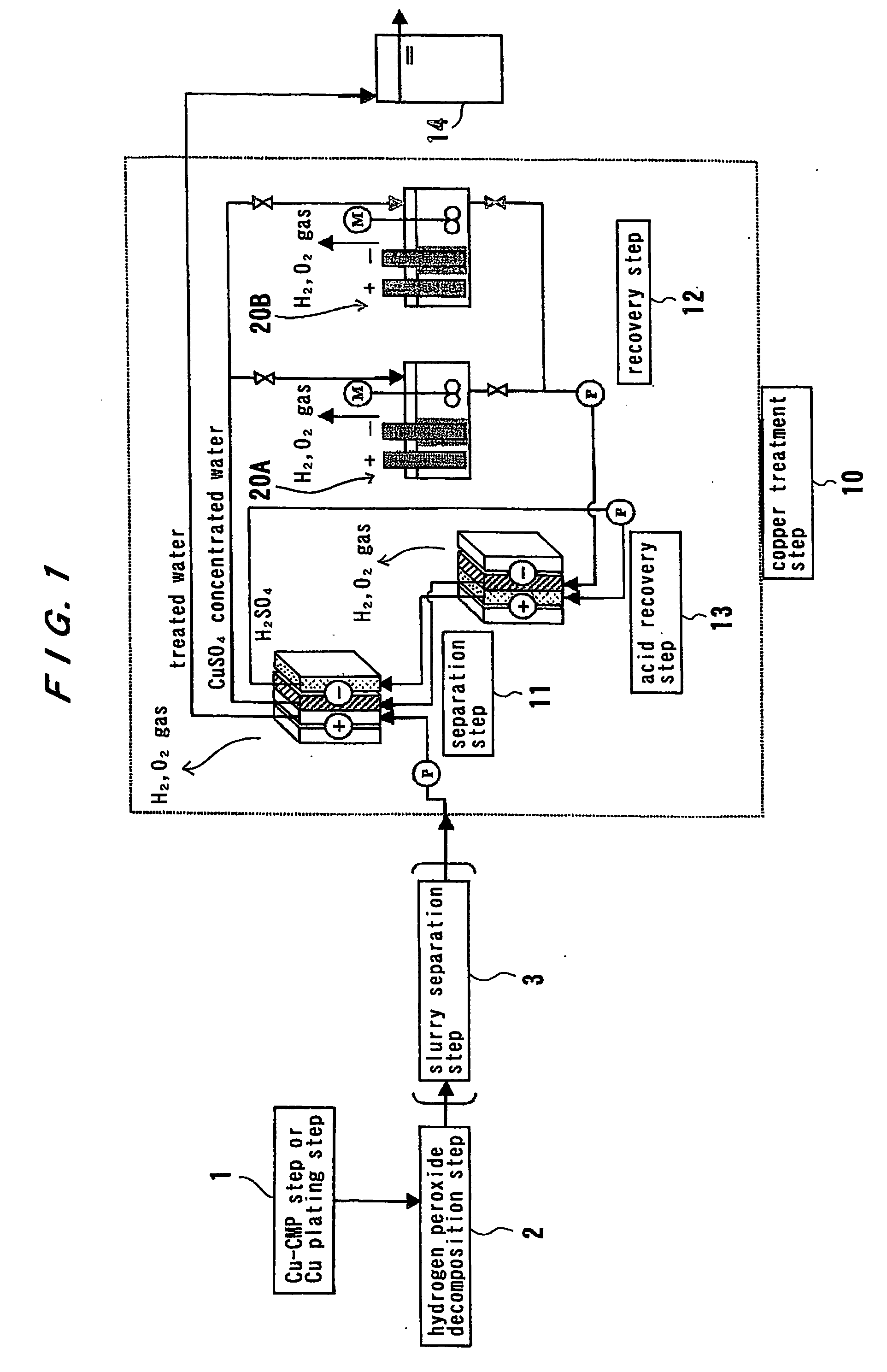
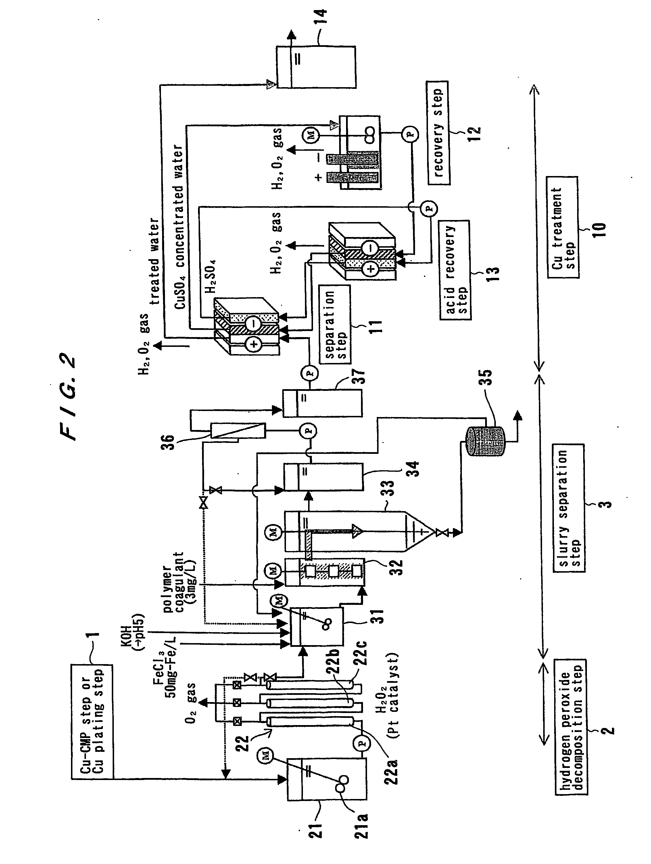
[0201] Slurry-suspended Cu-CMP waste water (TS: 2500 mg / l, Cu concentration: 100 mg / l, H2O2 concentration: 1000 mg / l, ζ potential of slurry: minus (negative) value (−20 mV or less) in a pH of 3 to 10 although the ζ potential varies depending upon pH) was adjusted to a pH of 5 by the addition of sulfuric acid, and then hydrogen peroxide in the waste water is decomposed in a hydrogen peroxide decomposition apparatus shown in FIG. 3. A catalyst-packed tower having a three-column structure was used. A gas-liquid separator was provided between adjacent columns to remove an oxygen gas generated by the decomposition of hydrogen peroxide.

[0202] The treatment was carried out under conditions of water flowing speed 30 m / hour and contact time 3 minutes (in total of three columns). The catalyst used was a platinum-coated metal honeycomb catalyst (having an acid-resistant coating), and had a pore density of 500 cell / square inch. The amount of platinum coated by the metal honeycomb catalyst was ...


PUM

PropertyMeasurementUnit
widthaaaaaaaaaa
concentrationaaaaaaaaaa

Abstract

The present invention relates to a method and apparatus for removing and recovering metal such as copper from various kinds of waste water containing copper. A method for treating waste water includes treating waste water in a copper treatment step (10) comprising a combination of electrodialysis operation and electrolytic deposition operation to produce treated water (107) having a lowered copper concentration, and recovering copper from the waste water.

Description

TECHNICAL FIELD [0001] The present invention relates to a method and apparatus for removing and recovering metal such as copper from various kinds of waste water to be treated. BACKGROUND ART [0002] In a case of treating waste water containing heavy metal, such as waste water produced in plating, waste water produced in semiconductor device fabrication processes, waste water produced in fabrication of printed circuit boards, or waste water produced in mines, it has been required to remove heavy metal from waste water and recover the heavy metal as needed. [0003] For example, in fabrication processes for semiconductor devices such as semiconductor integrated circuits, demands for semiconductor devices having finer interconnections or elements have further increased in recent years to thereby cause a problem of signal delay due to interconnection resistance. In order to solve this problem, aluminum or tungsten is replaced with copper for interconnections. [0004] Specifically, as semic...

Claims


Application Information

Patent Timeline
Patent Type & Authority Applications(United States)
IPC IPC(8): G01N27/26C02F1/42C02F1/461C02F1/467C02F1/469C02F1/52C02F1/56C02F1/66C02F1/70C02F9/00C22B7/00C22B15/00C25C1/12C25D21/16
CPCC02F1/42C02F1/4678C25D21/16C25C1/12C02F1/4693C02F1/4695C02F1/5236C02F1/56C02F1/66C02F1/705C02F9/00C02F2001/46152C02F2101/20C02F2103/346C02F2201/46125C22B7/006C22B15/0086Y02P10/20
Inventor NAKAGAWA, SOTAAKAHORI, MASAJIKASHIWAGI, MAKOTOMAISHIGI, KEIJI
Owner EBARA CORP
Why Eureka
Try Eureka