
Carbon material and method for producing same

a carbon material and carbon technology, applied in the field of new structure and production, can solve the problems of large form, low hardness and hardness of graphite as compared with those of metallic materials, and relatively easy slippage, and achieve the effects of reducing cost, simple process, and greatly enhancing productivity

Active Publication Date: 2012-03-29
INCUBATION ALLIANCE
View PDF3 Cites 63 Cited by
  • Summary
  • Abstract
  • Description
  • Claims
  • Application Information

AI Technical Summary

Benefits of technology

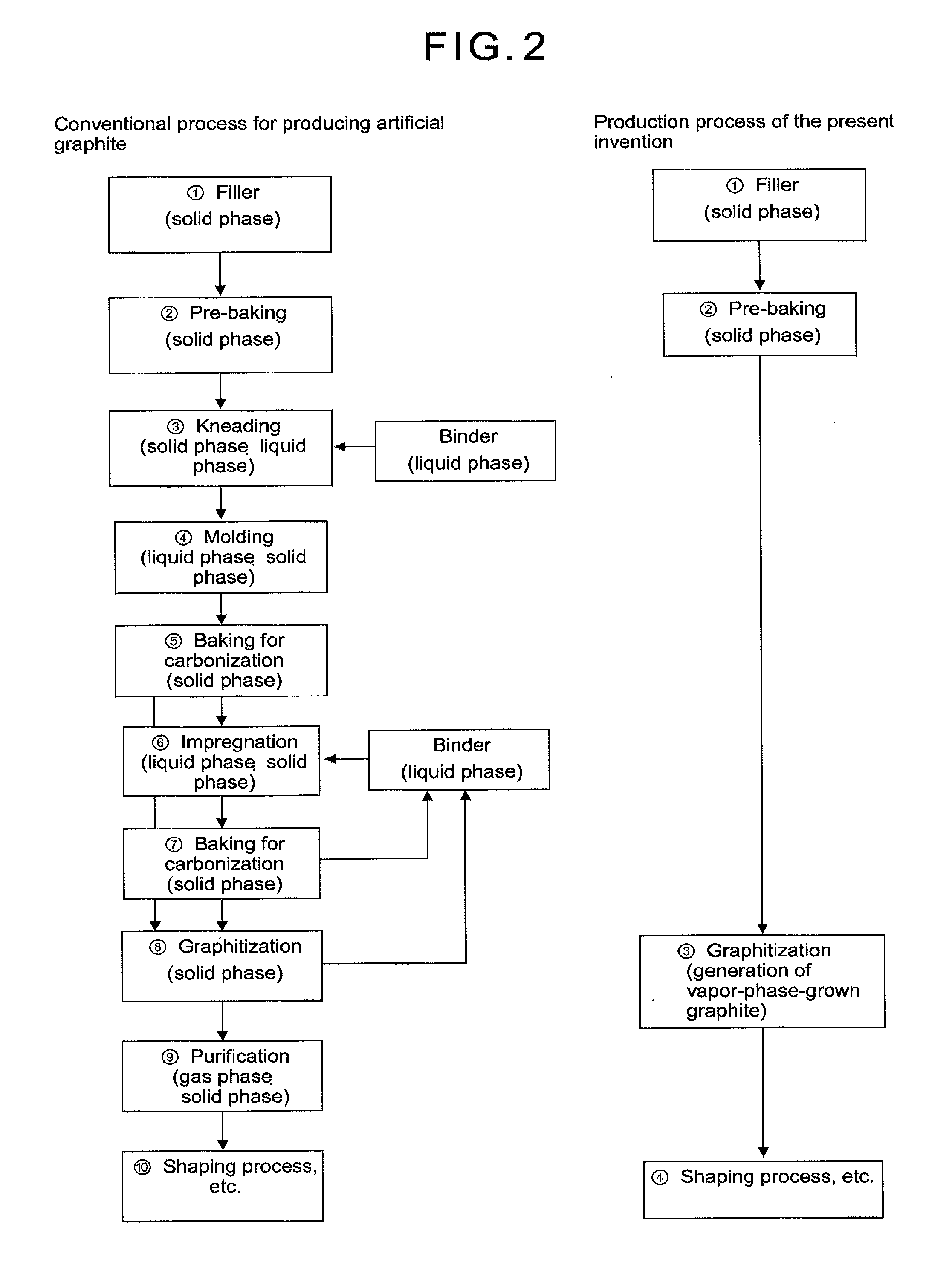
[0070]In the first aspect of the present invention, as mentioned above, the method for producing an artificial graphite material by a simple process as compared with conventional method was invented. By this method, a period of time for production which has been two to three months can be shortened to about one week, productivity is greatly enhanced to enable decrease in cost. In applications to fuel cells and capacitors, in which cost of carbon materials is high, it is expected diffusion is promoted due to decrease in cost.
[0071]In the first aspect of the present invention, in order to produce graphite by vapor phase growth, it is possible to design and produce porous and high density graphite materials having ideal crystal structure and crystal size. In addition, it is possible to provide electrode materials having an ideal structure for batteries such as lithium ion batteries and hybrid capacitors utilizing a reaction for generating a graphite intercalation compound because a thin material, in which edge portions of carbon hexagonal planes face toward a plane direction of the material (conventionally in the case of a thin material, carbon hexagonal planes gather on the surface of the material), can be produced. Further, it is possible to produce and provide an ideal material for applications to a diffuser panel for fuel cell where graphite materials having good gas permeability because of proper open pores, high electric conductivity due to high graphite crystallinity, high purity and high strength are required.
[0072]Also, since it is possible to make on a massive scale at a low price a carbon fiber-reinforced carbon material, a carbon fiber-reinforced graphite material, a graphite sheet, a carbon nanotube, a carbon nanofiber, fullerene, a carbon nanohorn, and a composite material thereof, application of these materials is expected to be promoted and enlarged. While carbon nanomaterials, thin films and fibers have been produced by various vapor phase reactions, obtained materials were nano structures and thin films, and in order to form them into optional shapes, separate steps were required. FIG. 4 compares the conventional method for vapor phase growth and the present invention with respect to production processes and obtained shapes.
[0073]In the second aspect of the present invention, nanocarbon materials can be produced by a CVD reaction using a general large size HIP equipment and a vessel made of a heat resistant material such as graphite as a reaction vessel, and therefore, productivity is enhanced significantly and materials of low price can be provided. Specifically it becomes possible to charge a starting material of 10 ton / batch in large-scaled HIP equipment being currently available on the market, and production of 5 ton / batch per day at yield of 50% can be obtained.
[0074]In addition, it is possible to allow a filler to carry a catalyst for generating a nanocarbon material directly thereon or to carry a nano size catalyst ionized in a solution thereon, and therefore, a nanocarbon material such as CNT of a desired shape having a controlled diameter can be produced with high selectivity.

Problems solved by technology

On the other hand, since the carbon hexagonal planes are weakly bonded to each other by so-called Van der Waals force, slip occurs relatively easily between the planes, and as a result, graphite has lower strength and hardness as compared with those of metallic materials and has self-lubricating property.
Since natural graphite produced naturally is a polycrystalline material, breakdown occurs at an interface of crystal grains and natural graphite is produced in a flaky form, not in a massive form having sufficient hardness and strength.
Therefore, anisotropy tends to be increased and as a result, a bulk density and a mechanical strength tend to be decreased.
In the case of artificial graphite and high density isotropic graphite, the graphitization proceeds in a liquid phase or a solid phase, and therefore even if heat treatment is carried out for a long period of time at a temperature of as high as 3000° C. or more, complete crystallization (graphitization) is difficult, a density of the graphite does not reach a theoretical density of 2.54 g / cm3, and there is a limit in a crystal size thereof.
However, an upper limit of the film thickness is several millimeters.
However, in such a temperature range, a transition metal as a catalyst is liquefied and vaporized, and a function of the catalyst is not exhibited.
However, a large-sized reactor is required and yield obtained is extremely low, and therefore, a mass production method has been studied.
However, any of them are produced by the same method as in fullerene, and in many cases, carbon materials other than CNT are produced secondarily and a selective production method has not been established.

Method used


Image

  • Carbon material and method for producing same
  • Carbon material and method for producing same
  • Carbon material and method for producing same

Examples


example 1

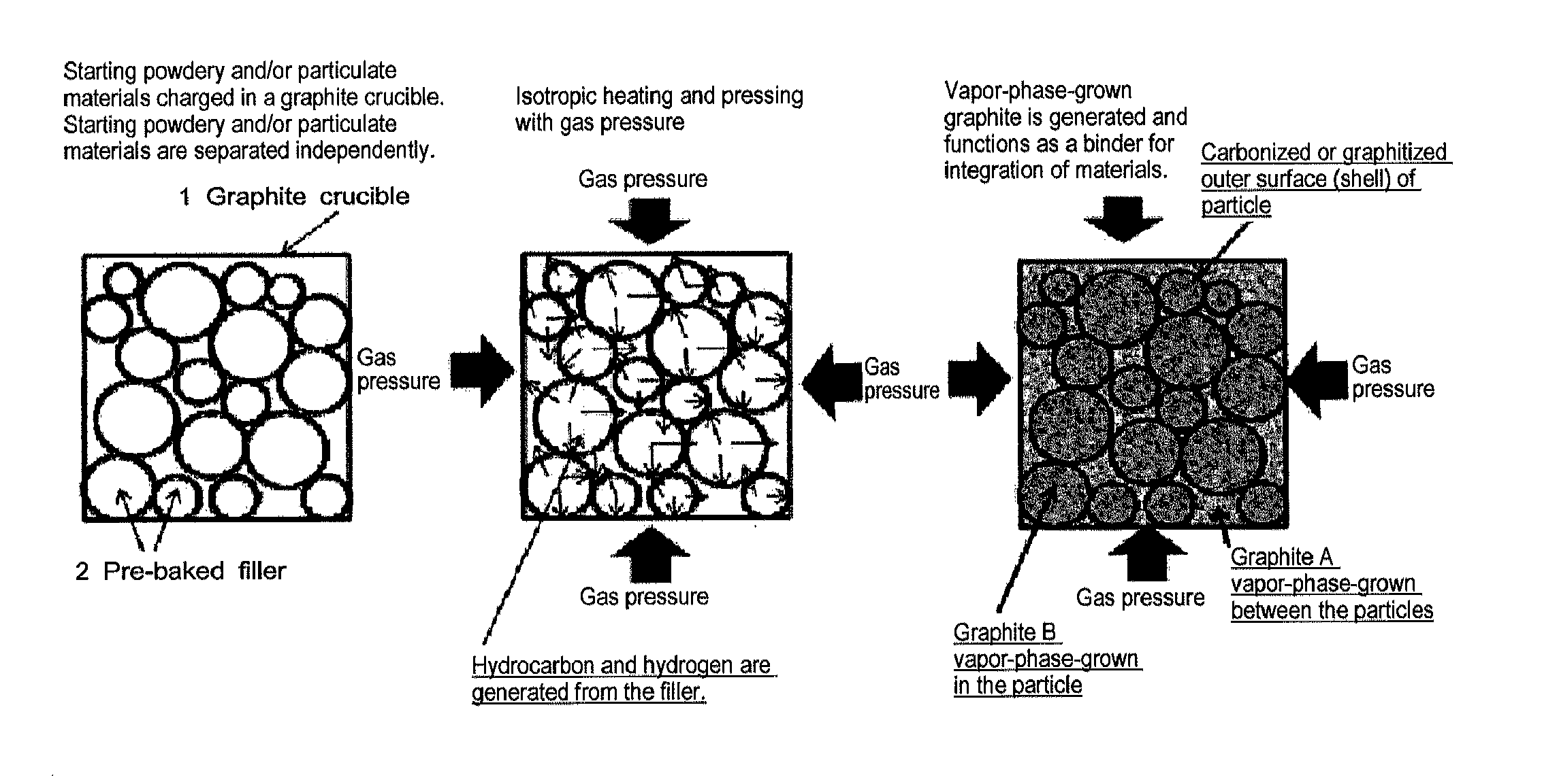
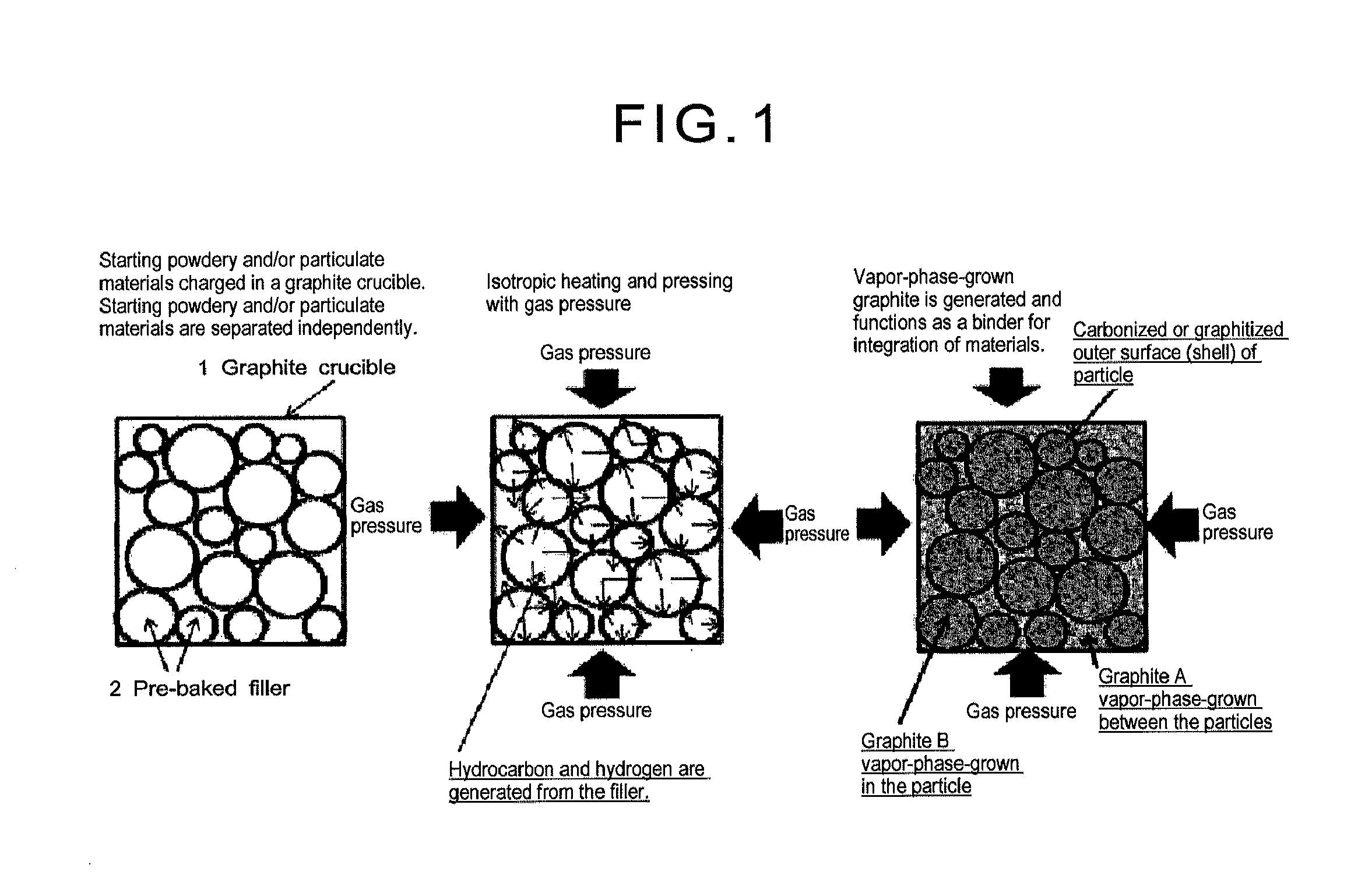
[0220]Phenol formaldehyde resin powder having an average particle size of 20 μm was pre-baked at 750° C. in an inert gas atmosphere. The amount of hydrogen contained in the starting material after the pre-baking was 0.8% by weight. The pre-baked starting material powder was charged in a graphite crucible and a screw type top cover was closed to seal the crucible. FIG. 8 is an electron microscope photograph of the starting material after the pre-baking, and at this stage, the starting material exhibits forms of thermosetting resin and hard carbon (hardly graphitizable carbon).

[0221]As a material for the graphite crucible, isotropic graphite having a bulk density of 1.85, an open pore ratio of 8%, a porosity of 2 μm, a heat conductivity of 140 W / (m·K) and inner dimensions of φ50×100 mm was used. After the sealing, the graphite crucible was charged in hot isostatic pressing equipment, and then the inside temperature and pressure were increased to reach 700° C. and 70 MPa, respectively ...

example 2

[0228]Phenol formaldehyde resin powder having an average particle size of 20 μm was pre-baked at 750° C. in an inert gas atmosphere. The pre-baked starting material powder was charged in a graphite crucible and a screw type top cover was closed to seal the crucible. As a material for the graphite crucible, isotropic graphite having a bulk density of 1.85, an open pore ratio of 8%, a porosity of 2 μm, a heat conductivity of 140 W / (m·K) and inner dimensions of φ50×100 mm was used. After the sealing, the graphite crucible was heated up to 700° C. in one hour in argon gas stream, followed by heating up to a maximum ultimate temperature of 2000° C. at a temperature elevating rate of 500° C. per hour, holding that temperature for one hour and then decreasing the temperature to room temperature. A required period of time between charging to and discharging from the graphite crucible was 22 hours. The top cover of the graphite crucible was opened and the material inside the crucible was dis...

example 3

[0229]Phenol formaldehyde resin powder having an average particle size of 20 μm was subjected to baking for carbonization at 1200° C. in an inert gas atmosphere. The amount of hydrogen contained in the starting material after the baking was 0.05% by weight. The baked starting material powder was charged in a graphite crucible and a screw type top cover was closed to seal the crucible. After the sealing, the graphite crucible was charged in hot isostatic pressing equipment, and then the inside temperature and pressure were increased to reach 700° C. and 70 MPa, respectively in one hour using argon gas, followed by heating and pressing up to a maximum ultimate temperature of 2100° C. and a maximum ultimate pressure of 200 MPa, respectively at a temperature elevating rate of 500° C. per hour, holding the temperature and pressure for one hour and then decreasing the temperature to room temperature and lowering the pressure. The top cover of the graphite crucible was opened and the mater...


PUM

PropertyMeasurementUnit
Fractionaaaaaaaaaa
Fractionaaaaaaaaaa
Percent by massaaaaaaaaaa

Abstract

(Problem)In conventional method for producing artificial graphite, in order to obtain a product having excellent crystallinity, it was necessary to mold a filler and a binder and then repeat impregnation, carbonization and graphitization, and since carbonization and graphitization proceeded by a solid phase reaction, a period of time of as long as 2 to 3 months was required for the production and cost was high and further, a large size structure in the shape of column and cylinder could not be produced. In addition, nanocarbon materials such as carbon nanotube, carbon nanofiber and carbon nanohorn could not be produced.(Means to Solve)A properly pre-baked filler is sealed in a graphite vessel and is subsequently subjected to hot isostatic pressing (HIP) treatment, thereby allowing gases such as hydrocarbon and hydrogen to be generated from the filler and precipitating vapor-phase-grown graphite around and inside the filler using the generated gases as a source material, and thereby, an integrated structure of carbide of the filler and the vapor-phase-grown graphite is produced. In addition, nanocarbon materials are produced selectively and efficiently by adding a catalyst or adjusting the HIP treating temperature.

Description

TECHNICAL FIELD[0001]The present invention relates to a novel structure and production method of an artificial graphite material which is used on electrode materials and diffusion layer for lithium ion battery, lithium ion capacitor, fuel cell, primary battery, second battery, steel making, refining and electrolysis, crucible for crystal growth of crystalline silicon and silicon carbide, insulating material and reactor for nuclear electric power generation.[0002]The present invention relates to a method for producing nanocarbon materials such as a carbon nanotube, carbon nanohorn, graphene and fullerene which are practically used for hydrogen storing material for fuel cell-powered vehicle, catalyst-carrying substrate, electrodes for field emission display (FED) assuring low power consumption, high luminance and low dependency on view angle and having self-luminescence in the fields of information home appliances, probe of tunneling microscope, an additive used for a conductive sheet...

Claims


Application Information

Patent Timeline
IPC IPC(8): B32B3/26D01F9/12C01B31/04B23H1/00B26D3/00C01B31/02D02G3/00B82Y30/00B82Y40/00H01G11/32H01G11/34H01G11/36H01G11/84
CPCB82Y30/00Y10T428/298C01B31/0213C01B31/0226C01B31/0293C01B31/0446C01B2202/36H01G11/32H01G11/34H01G11/36H01G11/84H01M4/587H01M4/62H01M4/625H01M4/8673H01M10/0525Y02E60/50Y02E60/13C01B31/04F16L59/028H01B1/04H01M4/583C01B31/022C04B35/52B29B13/021B29K2105/251C04B35/522C04B35/532C04B35/6325C04B35/6455C04B2235/3208C04B2235/3215C04B2235/40C04B2235/405C04B2235/422C04B2235/425C04B2235/428C04B2235/48C04B2235/5248C04B2235/526C04B2235/528C04B2235/5436C04B2235/72C04B2235/725C04B2235/728C04B2235/77B82Y40/00C01B32/158C01B32/16C01B32/18C01B32/184Y10T428/24999Y10T83/0591Y10T428/2918Y10T428/2982C01B32/156C01B32/154C01B32/159C01B32/205Y02E60/10C01B32/15C01B32/162C01B32/20C01P2004/32C01P2006/16C01P2004/64C01P2006/40H01M4/366
Inventor MURAMATSU, KAZUOTOYODA, MASAHIRO
Owner INCUBATION ALLIANCE
Learn More