Alkali Metal-Sulfur Secondary Battery Containing a Protected Sulfur Cathode and Manufacturing Method

a technology of sulfur cathode and secondary battery, which is applied in the manufacture of final products, cell components, electrochemical generators, etc., can solve the problems of dendrite formation, internal shorting, and state-of-the-art li-ion batteries that have yet to meet cost and performance targets, so as to reduce or eliminate the shuttling effect, block diffusion, and reduce the effect of

Active Publication Date: 2018-08-23
GLOBAL GRAPHENE GRP INC
View PDF0 Cites 62 Cited by
  • Summary
  • Abstract
  • Description
  • Claims
  • Application Information

AI Technical Summary

Benefits of technology

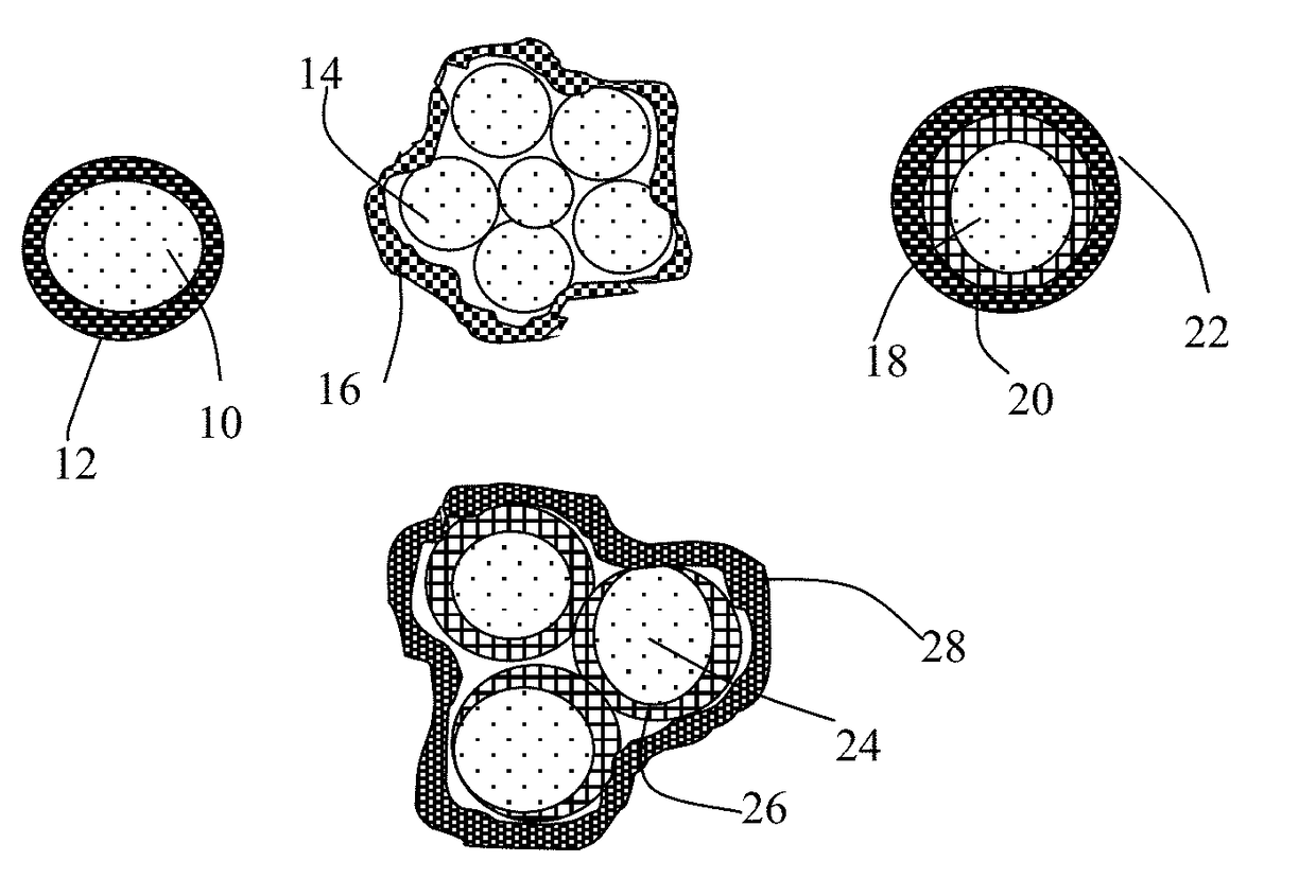
[0065]Also provided is a method of manufacturing a rechargeable alkali metal-sulfur cell selected from lithium-sulfur cell, sodium-sulfur cell, or potassium-sulfur cell. The method comprises: (a) providing an anode containing an anode active material layer and an optional anode current collector supporting the anode active material layer; (b) providing a cathode containing a cathode active material layer optionally supported on a cathode current collector; (c) providing a porous separator layer and an electrolyte and in ionic contact with the anode active material layer and the cathode active mate...

Problems solved by technology

Unfortunately, upon repeated charges/discharges, the lithium metal resulted in the formation of dendrites at the anode that ultimately grew to penetrate through the separator, causing internal shorting and explosion.
Although lithium-ion (Li-ion) batteries are promising energy storage devices for electric drive vehicles, state-of-the-art Li-ion batteries have yet to meet the cost and performance targets.
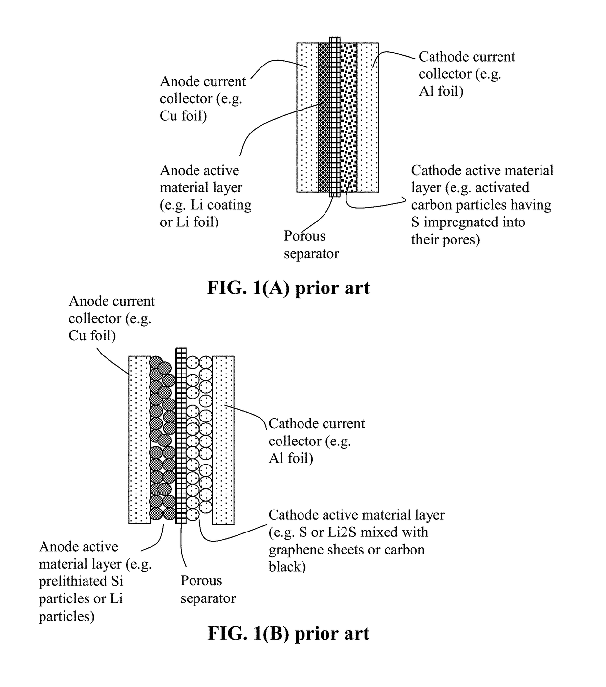
However, the current Li-sulfur cells reported by industry leaders in sulfur cathode technology have a maximum cell specific energy of 250-400 Wh/kg (based on the total cell weight), which is far below what is possible.
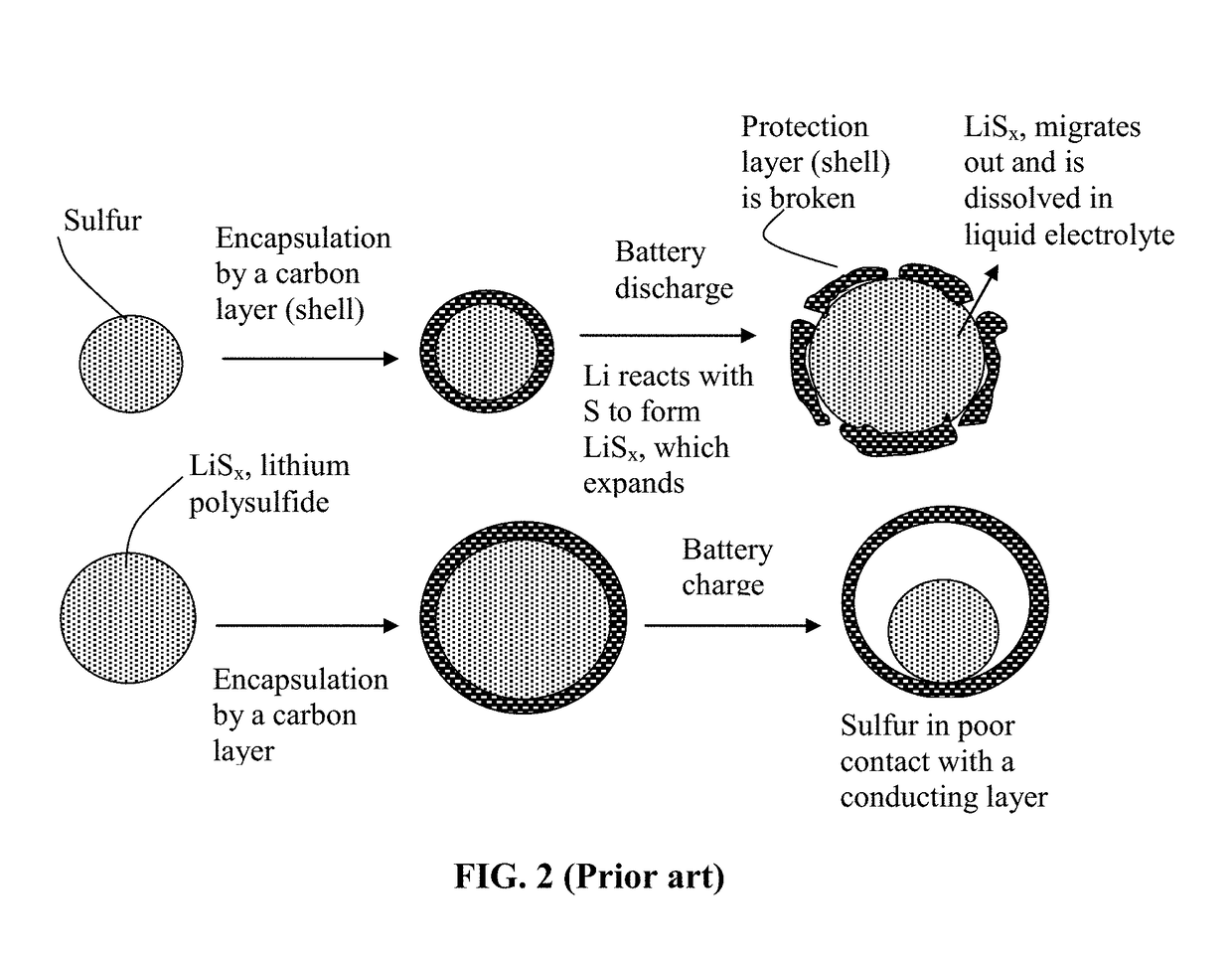
In summary, despite its considerable advantages, the Li—S cell is plagued with several major technical problems that have thus far hindered its widespread commercialization, as schematically illustrated in FIG. 2:(1) Conventional lithium metal cells still have dendrite formation and related internal shorting issues.(2) Sulfur or sulfur-containing organic compounds are highly insulating, both electrically and ionically.
Various carbon-sulfur composites have been utilized for this purpose, but only with limited success owing to the limited scale of the contact area.
This is mainly due to the high solubility of the lithium polysulfide anions formed as reaction intermediates during both discharge and charge processes in the polar organic solvents used in electrolytes.
In addition, the solid product that precipitates on the surface of the positive electrode during discharge becomes electrochemically irreversible, which also contributes to active mass loss.(4) More generally speaking, a significant drawback with cells containing cathodes comprising elemental sulfur, organosulfur and carbon-sulfur materials relates to the dissolution and excessive out-diffusion of soluble sulfides, polysulfides, organo-sulfides, carbon-sulfides and/or carbon-polysulfides (hereinafter referred to as anionic reduction products) from the cathode into the rest of the cell.
This process leads to several problems: high self-discharge rates, loss of cathode capacity, corrosion of current collectors and electrical leads leading to loss of electrical contact to active cell components, fouling of the anode surface giving rise to malfunction of the anode, and clogging of the pores in the cell membrane separator which leads to loss of ion transport and large increases in internal resistance in the cell.
Some interesting cathode developments have been reported recently to contain lithium polysulfides; but, their performance still fall short of what is required for practical applications.
However, the fabrication of the proposed highly ordered meso-porous ca...

Method used


Image

  • Alkali Metal-Sulfur Secondary Battery Containing a Protected Sulfur Cathode and Manufacturing Method
  • Alkali Metal-Sulfur Secondary Battery Containing a Protected Sulfur Cathode and Manufacturing Method
  • Alkali Metal-Sulfur Secondary Battery Containing a Protected Sulfur Cathode and Manufacturing Method

Examples


example 1

The Ethoxylated Trimethylopropane Triacrylate Monomer-Derived High-Elasticity Polymer

[0158]In a representative procedure, the ethoxylated trimethylopropane triacrylate monomer (ETPTA, Mw=428, Sigma-Aldrich) was dissolved in a solvent mixture of ethylene carbonate (EC) / diethyl carbonate (DEC), at a weight-based composition ratios of the ETPTA / solvent of 3 / 97 (w / w). Subsequently, benzoyl peroxide (BPO, 1.0 wt. % relative to the ETPTA content) was added as a radical initiator to allow for thermal crosslinking reaction after mixing with cathode particles. Then, cathode active material particles (e.g. S-graphene particles) were dispersed in the ETPTA monomer / solvent / initiator solution to form a slurry, which was spray-dried to form ETPTA monomer / initiator-embraced S-graphene particles. These embraced particles were then thermally cured at 60° C. for 30 min to obtain the particulates composed of S-graphene particles encapsulated with a thin layer of a high-elasticity polymer. The ETPTA po...

example 2

Preparation of Cyano-Ethyl Polyvinyl Alcohol-Derived High-Elasticity Polymer

[0162]The high-elasticity polymer for encapsulation of several sulfur- and lithium polysulfide-based cathode particles was based on cationic polymerization and cross-linking of the cyanoethyl polyvinyl alcohol (PVA-CN) in succinonitrile (SN). The procedure began with dissolving PVA-CN in succinonitrile to form a mixture solution. This step was followed by adding an initiator into the solution. For the purpose of incorporating some lithium species into th high elasticity polymer, we chose to use LiPF6 as an initiator. The ratio between LiPF6 and the PVA-CN / SN mixture solution was varied from 1 / 20 to ½ by weight to form a series of precursor solutions. Subsequently, particles of a selected cathode active material and their graphene-embraced versions were introduced into these solutions to form a series of slurries. The slurries were then separately subjected to a micro-encapsulation procedure to produce cathod...

example 3

Preparation of Pentaerythritol Tetraacrylate-Derived High-Elasticity Polymer

[0164]For encapsulation of sulfur-carbon, sulfur-graphite, and sulfur-polymer hybrid particles, pentaerythritol tetraacrylate (PETEA), Formula 3, was used as a monomer:

[0165]The precursor solution was typically composed of 1.5wt. % of PETEA (C17H20O8) monomer and 0.1 wt. % of azodiisobutyronitrile (AIBN, C8H12N4) initiator dissolved in a solvent mixture of 1,2-dioxolane (DOL) / dimethoxymethane(DME)(1:1 by volume). Different sulfur-based hybrid particles were added into the precursor solution and were encapsulated with a thin layer of PETEA / AMN / solvent precursor solution via the spray-drying method (some solvent evaporated, but some remained). The precursor solution was polymerized and cured at 70° C. for half an hour to obtain particulates composed of high-elasticity polymer-encapsulated particles.

[0166]The reacting mass, PETEA / AMN (without cathode particles), was cast onto a glass surface to form several fil...


PUM


Abstract

Provided is a rechargeable alkali metal-sulfur cell comprising an anode active material layer, an electrolyte, and a cathode active material layer containing multiple particulates of a sulfur-containing material selected from a sulfur-carbon hybrid, sulfur-graphite hybrid, sulfur-graphene hybrid, conducting polymer-sulfur hybrid, metal sulfide, sulfur compound, or a combination thereof and wherein at least one of the particulates is composed of one or a plurality of sulfur-containing material particles being embraced or encapsulated by a thin layer of a high-elasticity polymer having a recoverable tensile strain no less than 10% when measured without an additive or reinforcement, a lithium ion conductivity no less than 10−5 S/cm at room temperature, and a thickness from 0.5 nm to 10 μm. This battery exhibits an excellent combination of high sulfur content, high sulfur utilization efficiency, high energy density, and long cycle life.

Description

FIELD OF THE INVENTION[0001]The present invention provides a unique cathode composition and structure in a secondary or rechargeable alkali metal-sulfur battery, including the lithium-sulfur battery, sodium-sulfur battery, and potassium-sulfur battery. The lithium-sulfur battery can include the lithium metal-sulfur battery (having lithium metal as the anode active material and sulfur as the cathode active material) and the lithium ion-sulfur battery (e.g. Si or graphite as the anode active material and sulfur as the cathode active material). The sodium-sulfur battery can include the sodium metal-sulfur battery (having sodium metal as the anode active material and sulfur as the cathode active material) and the sodium ion-sulfur battery (e.g. hard carbon as the anode active material and sulfur as the cathode active material).BACKGROUND[0002]Rechargeable lithium-ion (Li-ion) and lithium metal batteries (including Li-sulfur and Li metal-air batteries) are considered promising power sour...

Claims


Application Information

Patent Timeline
IPC IPC(8): H01M4/36H01M4/62H01M4/38H01M4/587H01M4/58H01M4/60H01M10/0525H01M10/054
CPCH01M4/364H01M4/622H01M4/38H01M4/366H01M2004/028H01M4/5815H01M4/602H01M10/0525H01M10/054H01M4/587H01M4/62H01M4/625H01M10/052Y02E60/10Y02P70/50H01M2004/021
Inventor PAN, BAOFEIHE, HUIZHAMU, ARUNAJANG, BOR Z.
Owner GLOBAL GRAPHENE GRP INC
Why Eureka
Try Eureka