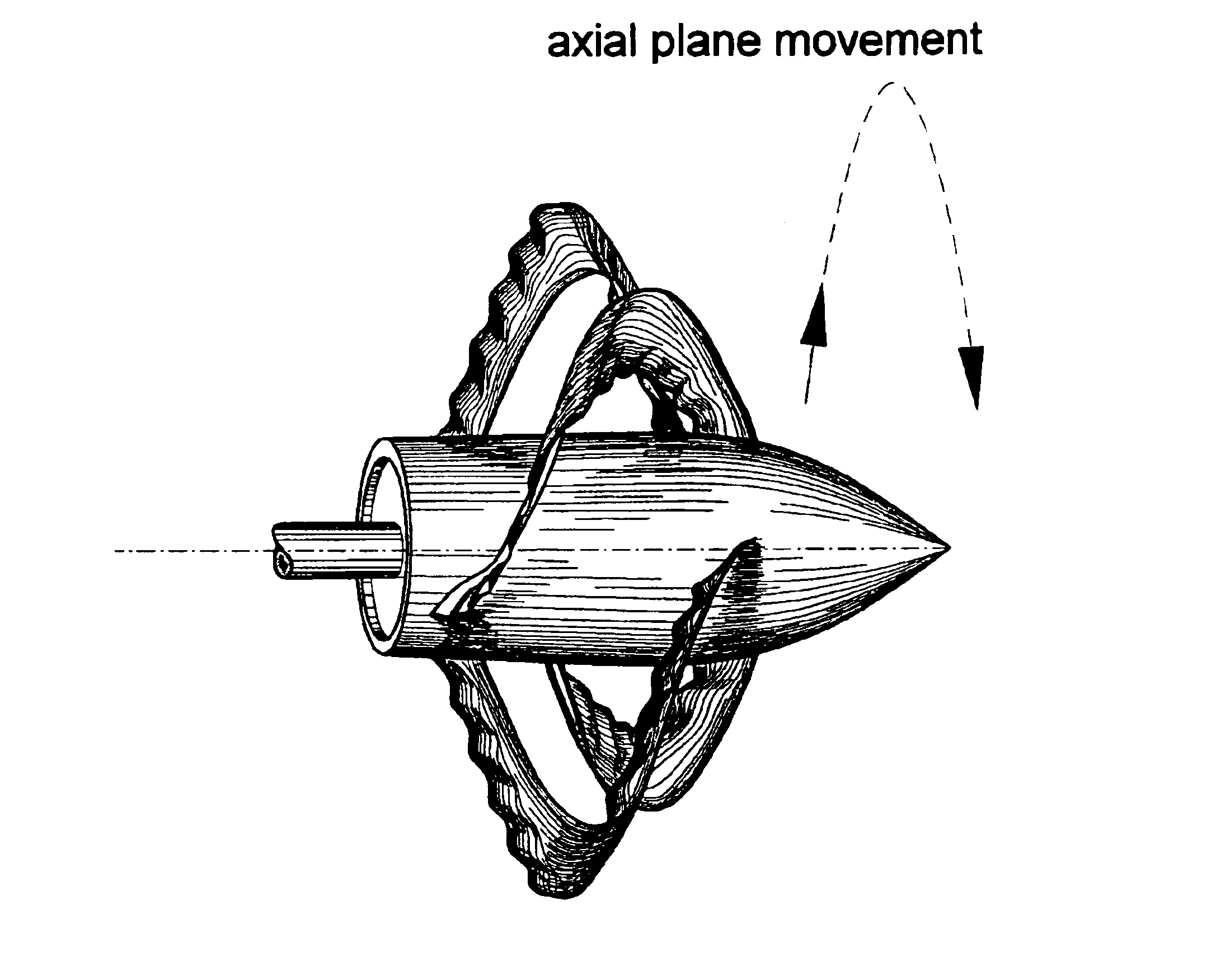
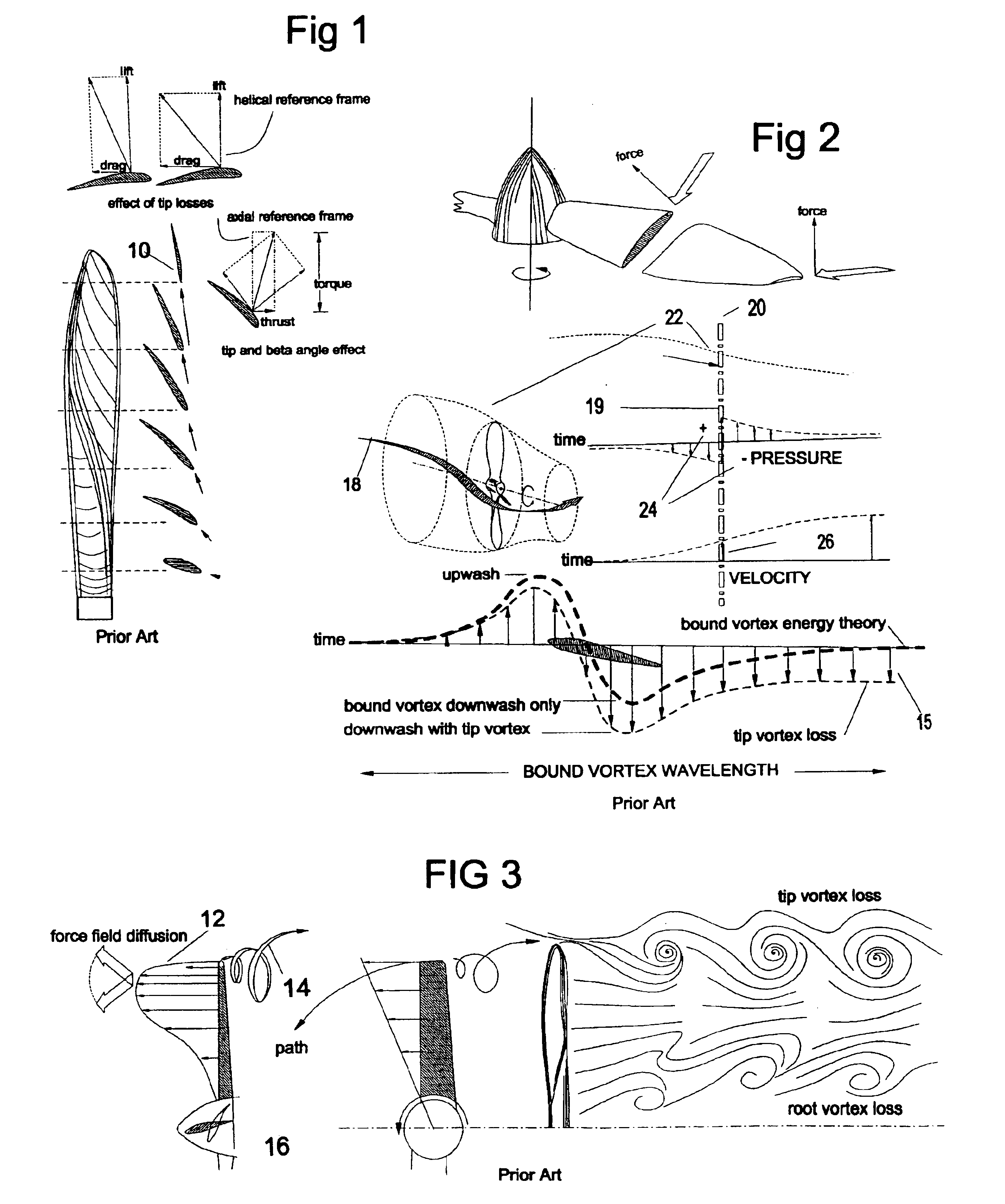
As shown in the lower illustration of FIG. 2, since drag due to—and induced by—lift in any tipped foil results in an increase of fluid acceleration—called induced downwash 15—inboard of the tip to offset the pressure lost to vortex formation at the tip, the disadvantageous
helix angles 16 of FIG. 3 on the left of the inboard portion of the
propeller disc spills significant energy by twisting the
slipstream 18 out of desired axial alignment resulting in root vortex losses.
In the case of the conventional wind
turbine, the highly loaded annulus 12 of FIG. 3 additionally imposes the characteristic uneven retardation on the flow streamlines on the right of FIG. 3, causing significant swirl and a thick sheet of discontinuity resulting in the well-documented
spillage of over half the theoretically available linear
kinetic energy.
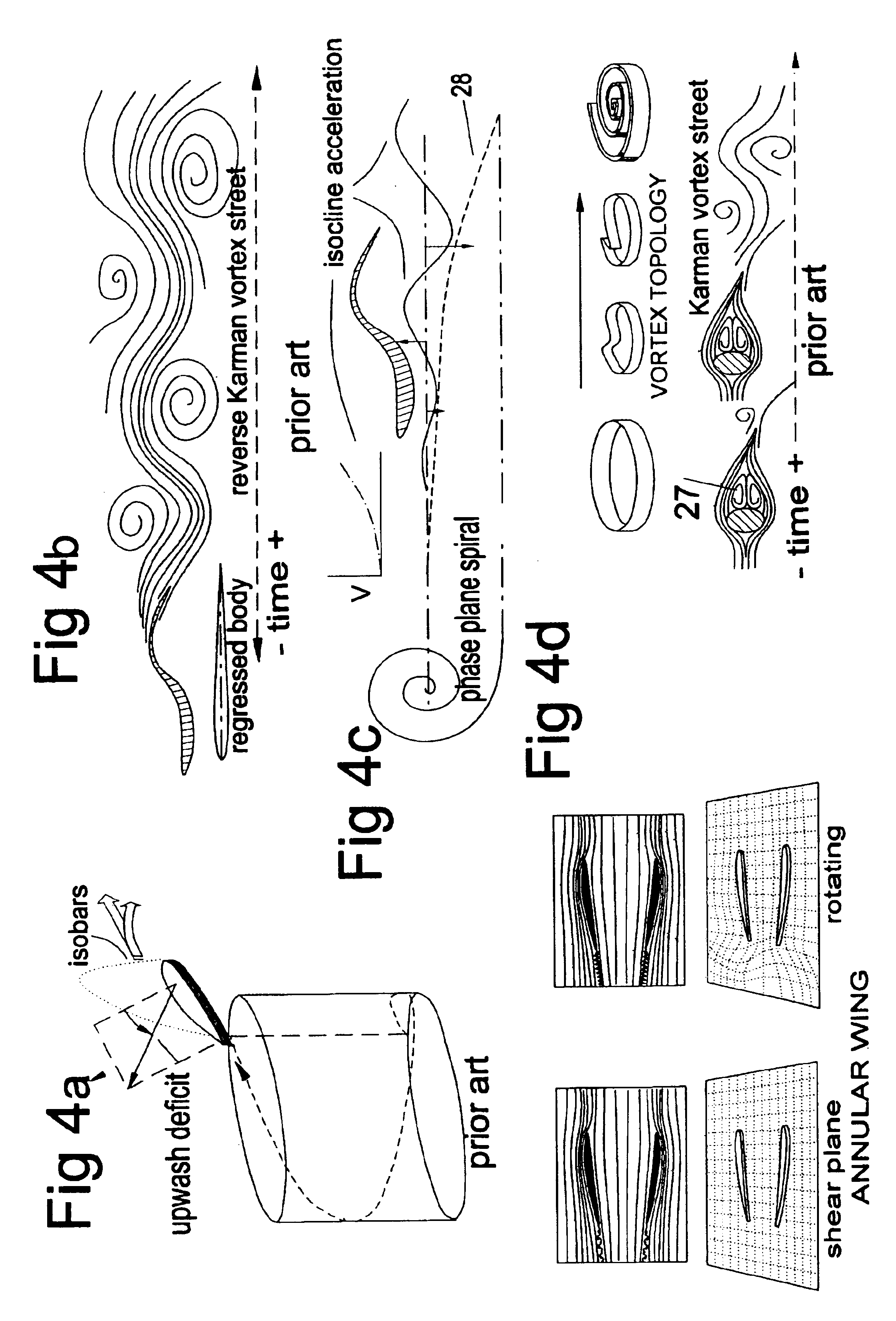
These vortex flows 14 additionally also have the
disadvantage of causing very high tip region spanwise flows and actual reversals of flow as shown on top of FIG. 9 with resulting boundary layer turbulence, loss of lift and low pressures that additionally occasion different design constraints in different applications:
Helicopter blade—even though the helicopter disc is not purely an axial flow device it nevertheless encounters similar constraints: vortex
noise, blade slap due to vortex buffeting and
harmonic and resonant oscillations due to rapidly changing differential pressures across the disc due to uneven pressure distribution.
Since—according to
Propeller Momentum Theory—efficiency is developed, and measured by the
momentum change involving the highest possible fluid
mass involving the smallest possible velocity change 26, this unopposed contraction—or its expansion in the case of the
turbine—, must also be considered a source of inefficiency through the resulting decremented mass flow rate in the conventional propeller.
An important structural limitation that results from this blade fluid dynamic that detracts from efficiency is the fact that structurally, a thin, twisted rotating bar of relatively flexible material somewhat akin to a single prong long
tuning fork—of low
natural frequency—, has
low resistance to Coriolis forces, disc loading
asymmetry, torsional, resonant and
harmonic oscillation and so needs a massive and fluid-dynamically inefficient blade root.
An additional fact is that the requirement of adequate starting performance combined with good
cruise performance occasions
cruise speed efficiency compromises caused by the propellers stated severe design constraints.
Because this force is a vector, rotation, which can only affect regions of fluid mass over a diffusing sector, involving the rate-of-change tangent-sector of the swept angle of tangential motion, this
helical path must itself also be considered a source of propeller inefficiency.
To sum the described deficiencies of rotation itself, partly owing to the continuing inscrutability of the phenomenon of turbulence, and partly due to the millennial legacy of rotation itself, is the practice of this art presently not well integrated with the more evolved time-domain practices in related fields that successfully apply the laws of
physics of
waves and oscillating systems.
As a consequence, the just described inefficiency of
helical motion artifacts and tipped-blade vortex that limit economic cost-benefit has been generally considered unamenable.
Time-invariant methods of analysis are particularly ill adapted to analyze forces resulting from unusual—namely linear
wave propagation—anguillar propulsive mechanisms, particularly those of nature.
For lack of comprehensive tools, however, previous attempts to introduce mechanical analogs of such promisingly efficient motions of nature as propulsive devices to the marketplace have suffered from inadequate precision of analysis, thus predictable manufacture, and have—so far—have been commercial failures.
As a three-dimensional secondary flow with its many
degrees of freedom is at present treated as heterogeneous turbulence by accepted practice, translation, sliding, flexing and undulation are also not rigorously modeled to acceptable standards of
engineering practice.
The economic investment necessary to generate such
theoretical models of nature has not yet been generally made available.
Thus, any motion that results in undulation as generated by rotation must involve highly complex compound artifacts involving changing reference frames and boundary layer interactions that
pose severe analytic difficulties using state of the art design tools.
As this latter parameter is the very basis of the
classical theory of lift, any design that cannot—due to these imponderabilities—predict inflow vector, cannot determine this circulation or the force of lift, or drag.
If lift cannot be determined, foil orientation is not precisely possible.
Without formulated precision of causal relationships, repeatable effects became difficult to achieve.
Without a fully rigorous fluid dynamic modeling of such flows—still out of reach—,
relative motion could not be determined.
Such devices' orientation to flow and thus pressure gradients could not be ascertained to satisfy the Blade Element Theory requirements as well as standards of manufacturing
repeatability.
Without time-domain inflow parameters, such attempts were limited to intuitive experimentation on the basis of trial-and-error and as commercial devices could not hope to compete with the considerable empirical theoretical
database of a highly refined
engineering practice benefiting from many decades of incremental data refinement.
Thus, according to
classical theory itself, dynamic flow streamlines lack a direct mechanism to make them stray out of alignment with the axial plane before the
trailing edge.
Thus the prime enabling mechanism of the device is the detachment of this ‘drag’ entrainment through shape sequence anguillar propulsion.2. Compound and variable
planform sweep of the rotor ‘blade’—as imposed by the embedded 3D spiral ‘time-
cam’—imposes well-documented disadvantageous spanwise flows and high form drag at economically useful lift coefficients that would negate much of the theoretical
advantage of the proposed devices, impose
high rate-of-change variations in circulation and lift and thus create unacceptable boundary layer turbulence drag as well as a low lift curve slope.
This presented a great conundrum in my initial investigations of these devices.
This imposes many tons of blade root and
tower base forces requiring expensive means to assure rigidity, resulting in devices whose aspect is industrially stark and obtrusive, provoking proven public resistance to these harsh intrusions upon cherished pristine and pastoral landscape.
Thus, it has become evident to myself and will also become apparent for anyone who has access to the tools of lift analysis and the flow net, that the Betz Limit—as being an artifact of the legacy orientation of the
Actuator Disc and affecting a
stream tube of
Disc diameter—is not directly applicable to this duct-based device, which should exceed this limit.
But as is shown in FIG. 13a, since any rigid object—especially a rigid
tail—cannot accommodate itself to the
high frequency wave potentials of the small waveless
harmonic component sub orbits, it develops an interfering phase
lag with the prime wave component, causing these disordered
high frequency energies to precipitate into rapidly pulsing vertical moments 61 at the
tail.
This results in the formation of a surface of discontinuity that acts as a barrier to the phase path continuity of particle orbits.
This
cascade ends in generating useless heat and sound.
This layer's behavior in flows containing shear-in-vector and turbulence is unfortunately not presently fully modeled by the scientific
community.
Thus, the possibility existed that these strategies, however promising, might well lack insight on some unexpected detrimental interactions, and thus unintended consequences.
Because of paucity of means I confined the design to purely
radial motion.
Soon however, depending on prevailing
viscosity, —through the mechanism of frictional entrainment—these intermix and accumulate to a thick envelope of violently turbulent particles 21 that are continuously losing
momentum to heat and creating large scrubbing drag coefficients.
This phenomenon increases drag through the mechanism of violent vortex-based intermixing of
layers of different levels of retardation causing
high velocity scrubbing of the surface and thus high frictional drag.
This ultimately causes the dynamic flow to detach from the surface, resulting in premature loss of lift, high drag and premature stall.
Even using moderate operating lift coefficients, the wake of a conventional propeller contains a
wide band—‘vortex sheer’—of this slowed material roiling with spiraling eddies which ultimately rolls up into large
diameter tip vortices causing the well documented losses due to induced drag.
Without consideration of the boundary layer, the practice of fluid dynamics would not be possible.
The underlying physical surfaces sliding through a given axial plane of the virtual element do in fact entrain additional boundary layer particles and thus generate additional viscous drag, but these experience neither steady nor uniformly adverse pressure gradients, as they constantly encounter rapidly changing pressure gradients.
Additionally, it has been proven that any such boundary layer ejection—using any available method—allows the generation of unusually
high lift coefficients before flow separation.
The employment of the
momentum transfer of the sliding resonant element
train for these novel
pressure wave artifacts could not, however, be contemplated by an academic model using rate-of-change invariant rigid foil theory.
Prior art inventions that did not decompose axial and
transverse velocity changes resulting from oscillation dynamics into
phase plane parameters of
wave frequency, propagation gradient, amplitude and envelope analysis, containing rate-of-change vectors, could not promulgate such procedural design elements, nor state their degree of expected benefit.
Such
yaw correction ability is of considerable benefit, since the conventional propeller-based turbine is known to severely
lag in
yaw-response that is known to impose severe performance and stability penalties.
These are intrinsically less resistant to torsion, experience high bending moments, and thus incur high levels of alternating stresses, resonant oscillations,
flutter and fatigue.
Due to their length to
mass ratio, large wind turbine blades are thus akin to a very long—and very expensive—resonant single prong tuning forks with intrinsically high root loads, susceptibility to inertial self-
coupling and
tower resonant
coupling instabilities and so present formidable
engineering challenges.
They thus need equally expensive measures to compensate—such as upwind operation, employment of expensive exotic structural materials and methods of manufacture, complicated
pitch changing mechanisms or teetering arrangements and massive blade roots with their weight and losses of efficiency.
Additionally, such wind turbines are notoriously difficult to control in regard to output regulation or resistance to high or variable winds and must simply be
shut down at relatively moderate wind speeds, just when wind energy is most available.
Their whistling
noise, visual flickering, lack of esthetics, lack of wide public acceptance—and marginal economic basis—has prevented their wide-scale adoption in areas of less than high average wind velocity and low
population density.
They therefore impose the additional expense of long distance electrical distribution on their economic cost basis.
Due to these factors—using the aforementioned relatively wasteful and expensive strategies—has a free
natural resource of almost unlimited potential for the production of low cost energy that does not generate
greenhouse gasses, so far produced only marginal and limited benefit to society at large.
As such it will tend to be inherently non-injurious to
wildlife, as well as unlikely to provoke the built-in involuntary human
physiological responses to the stroboscopic visual flickering of massive conventional turbine ‘blades’ that whistle the approach of a blade moving at guillotine-like velocities.
A severely fluctuating and wasteful pressure field propagation velocity,Resulting in wasteful force orientation andHigh torque for low thrust in propellers—or high drag for low torque in turbines—
Most of this flow
kinetic energy however, whether in rivers, tidal flows,
waves or wind itself, resides in diffuse flows of less than 5 meters per second; flows that present strategies and devices are not able to economically access.
Rather than being
high lift-to-drag devices, they generate high drag-to-lift.
They erect a barrier of discontinuity to what is essentially a fluid-wide energy continuum, thereby creating massive flow evasions, mass-flow
spillage through
divergence, circumvention and its turbulence.
They are thus unable to economically generate power for the overwhelming majority of the population living on the landmass that experiences wind resources that are Class 3 or less.
As these are attached at both ends and thus lack an open tip, they have no ready means of generating a strong conventional tip vortex.
In this way, previously unavailable resources could become available.
However, as all devices that rotate blades impose the previously described inefficiencies precisely because of the described upwash deficit caused by this rotation, helicity itself must therefore be transformed to the
linearity of
relative motion that is the prerequisite to the
fully developed upwash attending efficient,
fully developed bound vortex circulation.
Unless this is done, the convergent duct ‘funnel’ surface would become a barrier of discontinuity of helicoidal vortex sheet turbulence like that attending the conventional turbine and therefore unable to function —or be analyzed—as a Bernoulli Equation device.

